Last Updated: 05-16-2026
Vehicle: 2013 Mitsubishi Lancer ES
Crankshaft Position Sensor Replacement
Introduction:
One of the key subsystems in a vehicle is the ignition and engine management system. It is controlled and evaluated by the Engine Control Module (ECM). Proper engine operation depends on five essential factors working together in precise synchronization. These factors are fuel, air, spark, compression (pressure), and timing. If any of these elements are not functioning correctly, the engine may experience poor performance or failure. In this tutorial, the focus is on a key component of the ignition and timing system, the Crankshaft Position Sensor. This sensor is typically easy to replace. Its main role is to provide real-time data on crankshaft position and engine speed to the ECM. The ECM uses this information to control ignition timing and fuel injection accurately. This ensures proper and efficient combustion throughout the engine cycle.
Purpose and Functionality:
The relevance of the Crankshaft Position Sensor (CKP) is that it actively monitors and sends real-time data to the Engine Control Module (ECM). The ECM is the centralized computer responsible for overseeing the operation and functionality of the ignition system. It coordinates communication between the system’s individual components. The crankshaft position sensor measures the current position of the crankshaft, which directly affects the positioning of the pistons. For normal engine operation, the position and timing of the crankshaft are essential for maintaining synchronization throughout the system. When the crankshaft is in the correct position and timing is accurate, a signal is sent to the ECM. In turn, the ECM sends a signal to the ignition coil, which generates enough current to create a spark at the spark plug at the appropriate time.
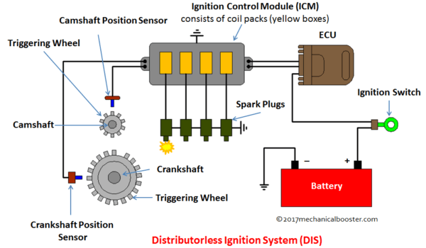
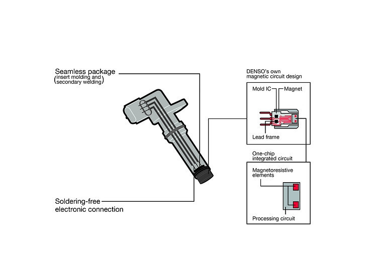
The inner operation of the Crankshaft Position Sensor involves a small air gap between the sensor and the reluctor wheel (gear). Inside the sensor, there is typically a magnet and a coil of wire that generates a small voltage as the gear teeth pass by. This process works through electromagnetic induction, and the resulting signal is interpreted by an internal processing circuit. The circuit converts the raw signal into a usable output, functioning in a way similar to an on/off switching signal.
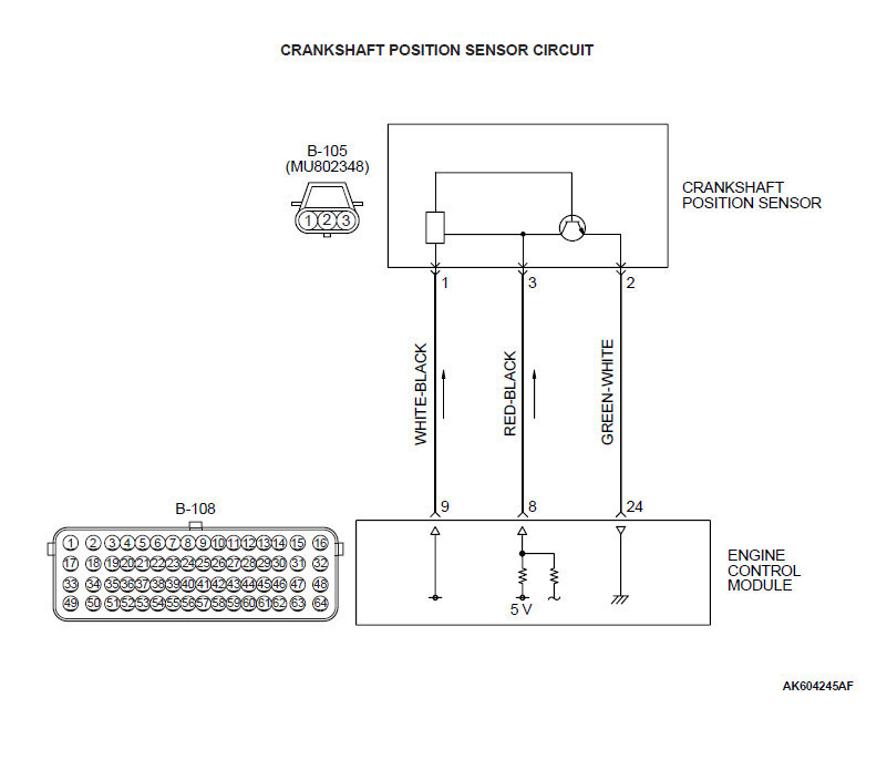
This data is then transmitted to the Engine Control Module (ECM) through a signal wire. In a 2013 Mitsubishi Lancer ES, the sensor typically has a three-pin setup consisting of a power supply, a signal wire (usually the middle pin), and a ground connection. The ECM receives this signal to determine crankshaft position and engine speed. These connections can be tested using a multimeter by checking voltage and continuity from the ECM side of the wiring harness rather than directly at the sensor. The diagram referenced is a generalized example and not an exact representation of the vehicle’s wiring, but it helps explain the basic operation and communication between the sensor and the ECM.
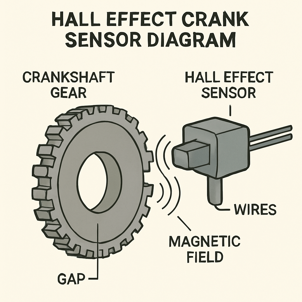
As shown below, there are three wires connecting to the processing unit and the sensor’s internal components. The positive and ground wires supply power to the processing unit and its required circuitry. The signal wire carries the output data from the sensor to the Engine Control Module (ECM). Inside the sensor, the magnetic field interacts with the passing gear teeth to generate a voltage. The processing unit then converts this voltage into a readable signal that the ECM can interpret to determine crankshaft position and engine timing.
Potential Failures of the Sensor:
- Corroded electrical connections
- Physical damage
- Fluid contamination
- Quality of design and parts
Symptoms of Malfunctioning Sensor Impacting the Vehicle:
- Engine light may be illuminated with the follow error codes:
- P0335 Crankshaft Position Sensor "A" Circuit Malfunction
- P0336 Crankshaft Position Sensor "A" Range/Performance
- P0337 Crankshaft Position Sensor "A" Circuit Low Input
- P0338 Crankshaft Position Sensor "A" Circuit High Input
- P0339 Crankshaft Position Sensor "A" Intermittent
- No start
- Engine Misfire
- Poor Acceleration
- Engine Stalling
Tools/Materials:
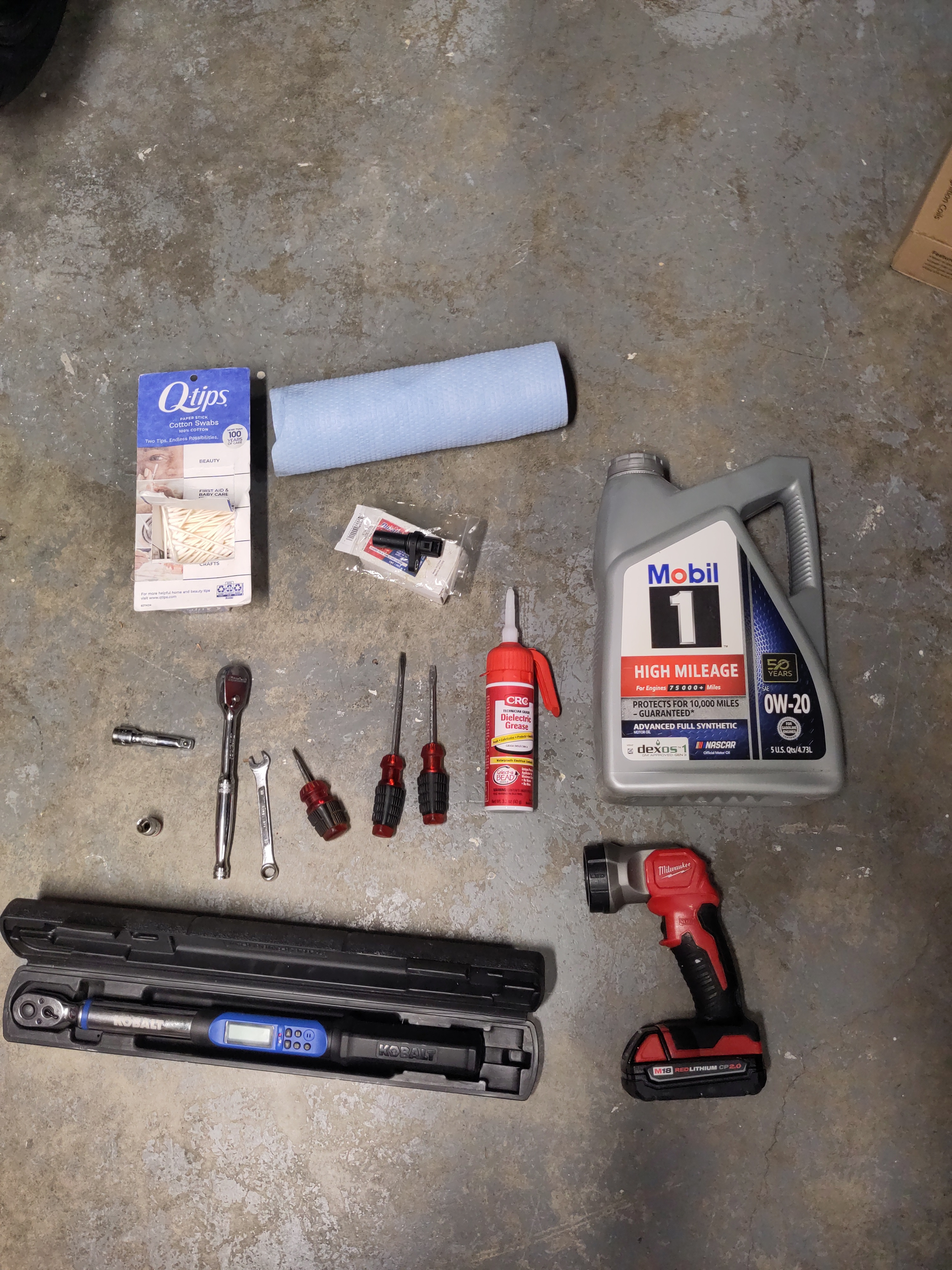
- Paper Towels
- 0W-20 Engine Oil
- New Crankshaft Position Sensor
- Q-tips
- Flashlight
- Dielectric Grease
- Different varying sizes of flat heads in length
- 3/8" Drive Socket Wrench
- 10mm Wrench
- 3/8" Drive 12mm socket
- 3/8" Drive extension
- 3/8" Drive Torque Wench(5-100 ft-lbs)
Removal of Sensor:
In this tutorial, it is assumed the 2013 Mitsubishi Lancer is already supported on jack stands, as this is required to access and replace the sensor. It is also assumed that the plastic underbody shields have already been removed from the vehicle. The tutorial will mention when these components need to be removed, but it will not explain the removal process in detail.
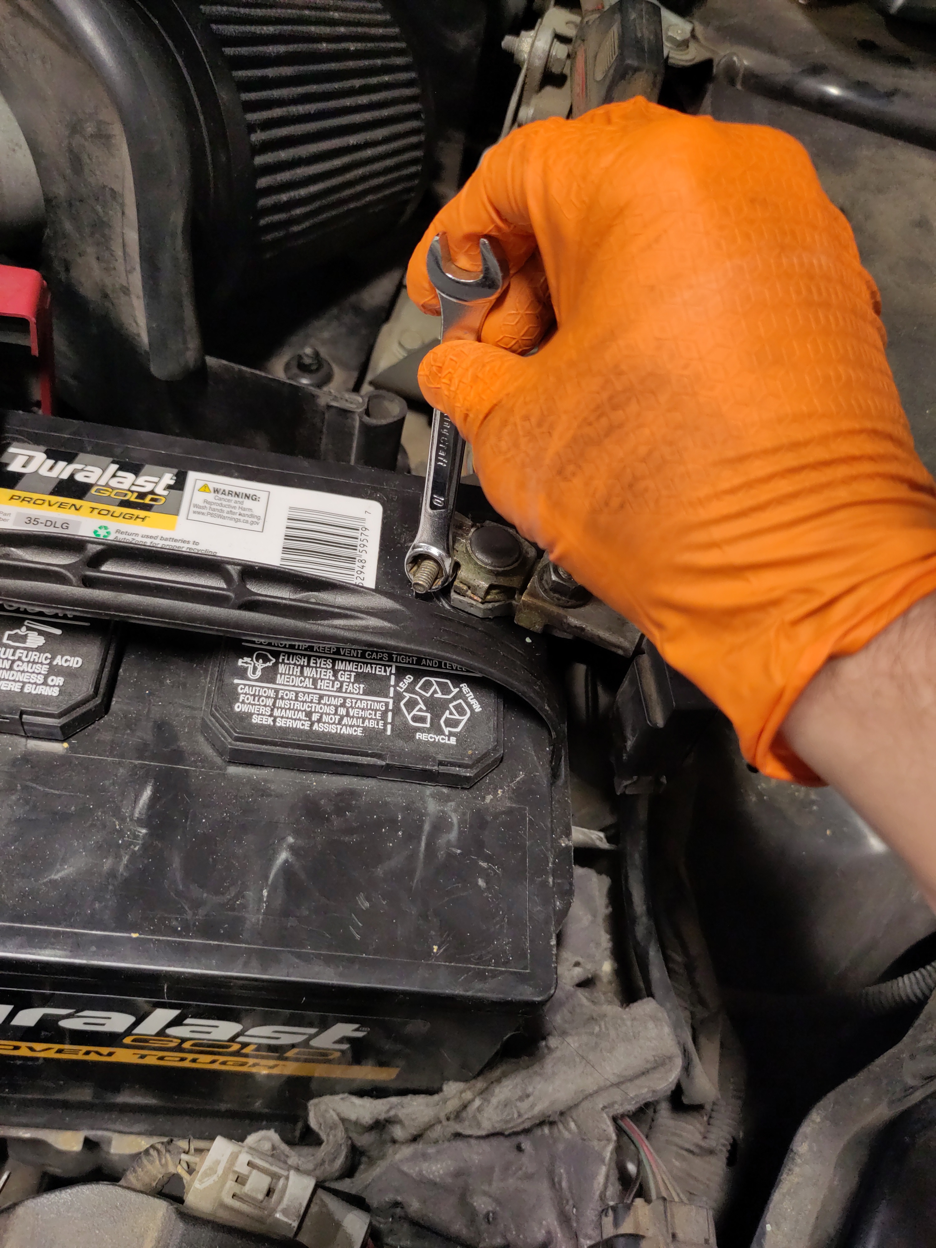
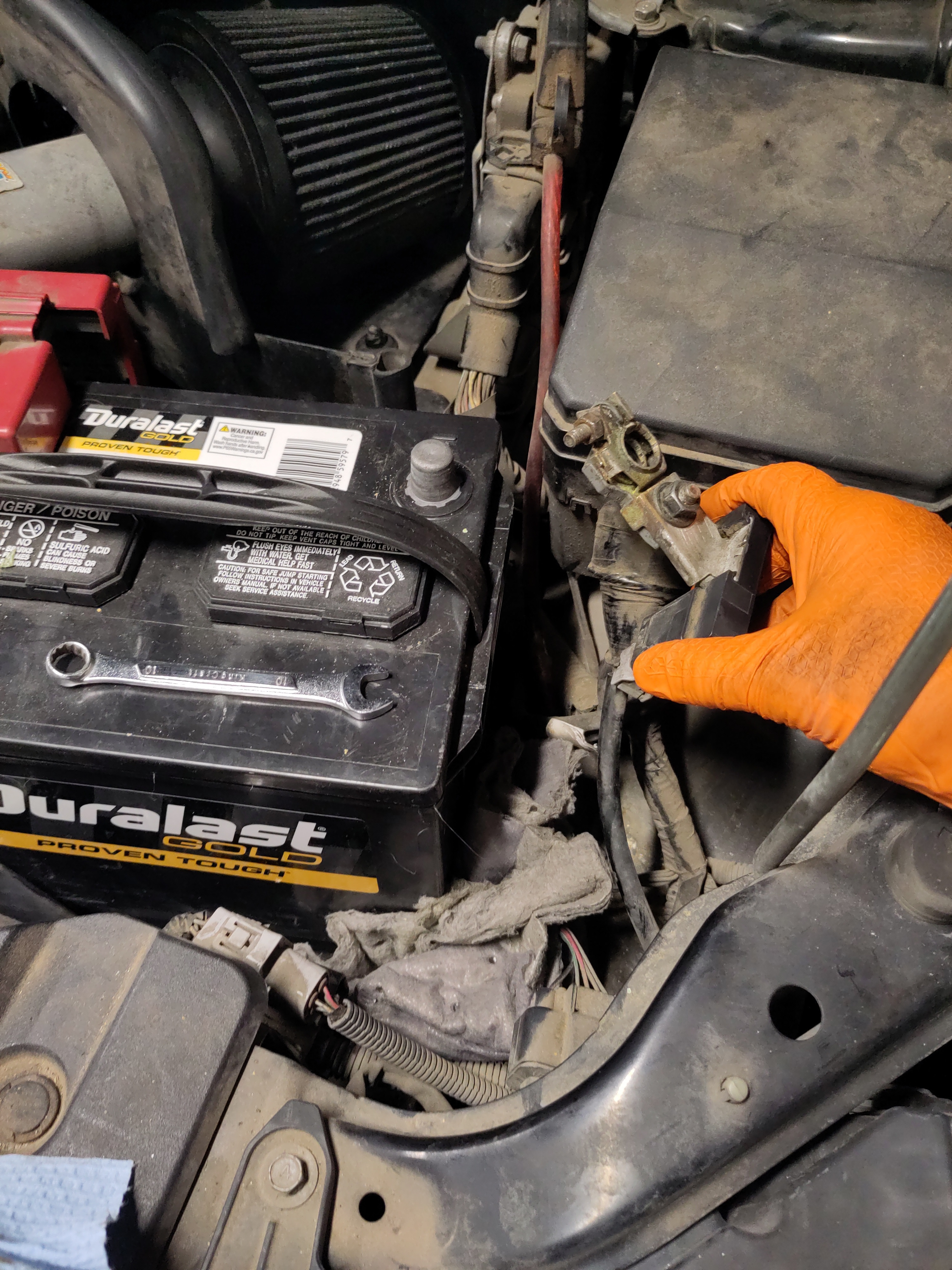
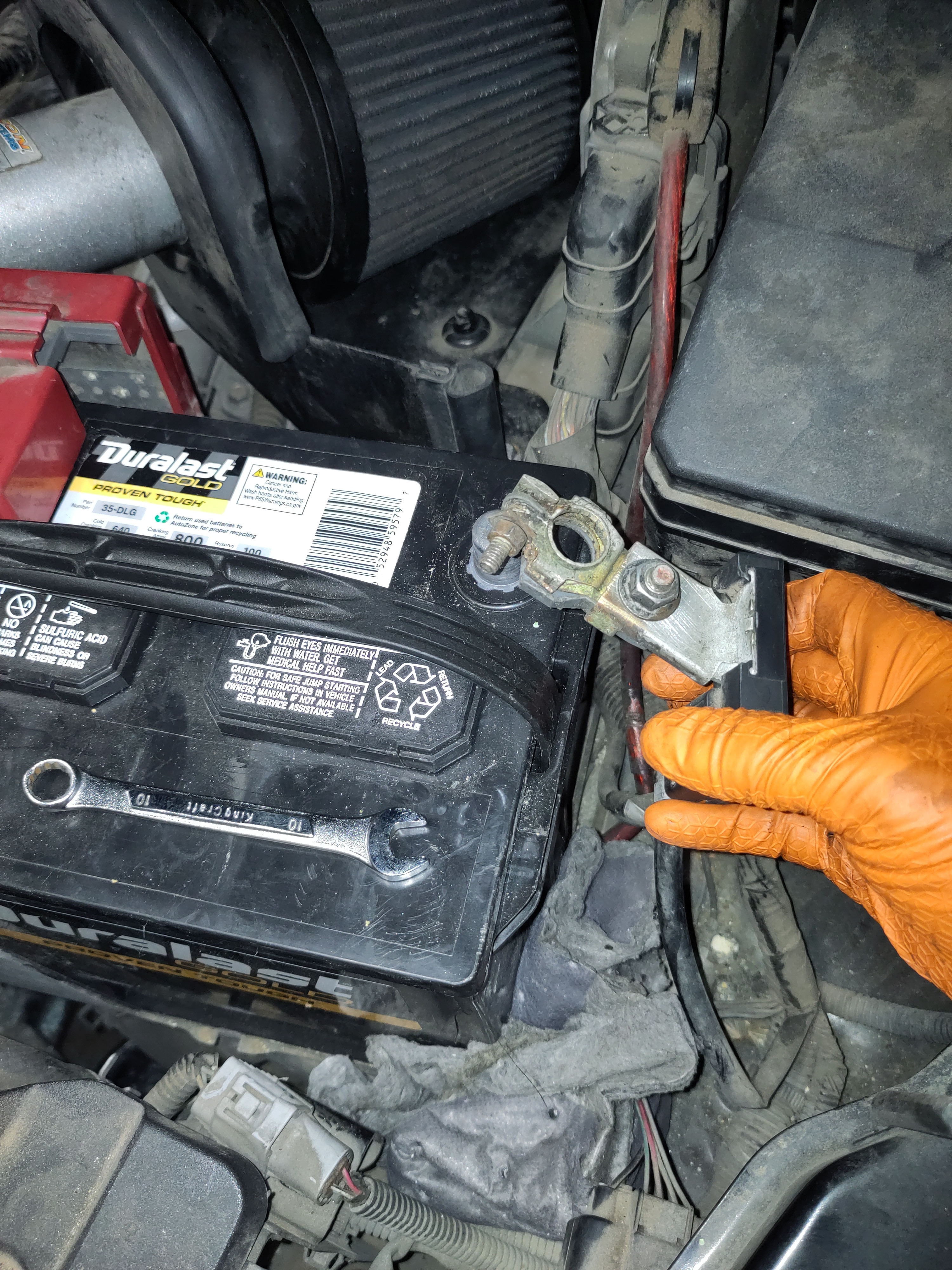
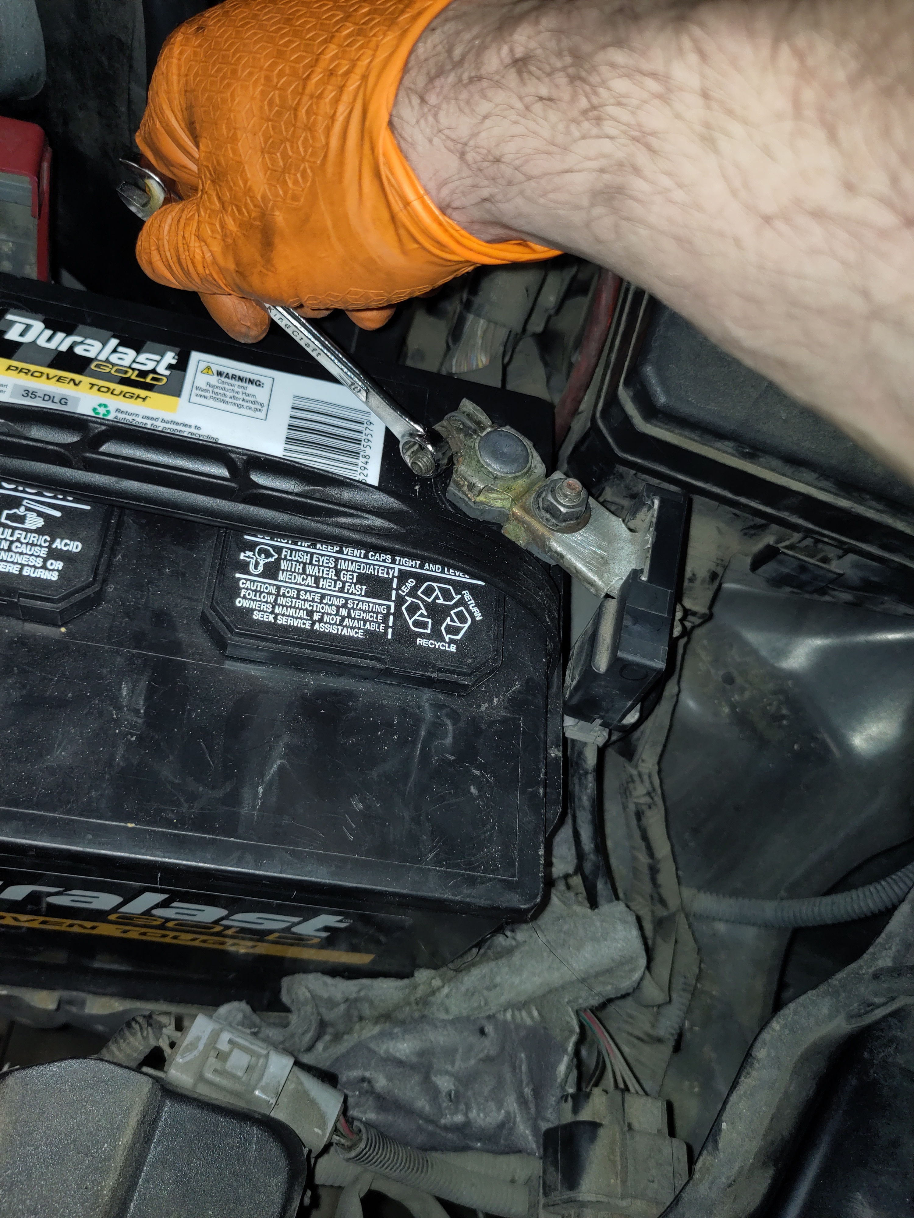
- Remove the Negative battery connection using a 10 mm wrench for safety purposes.
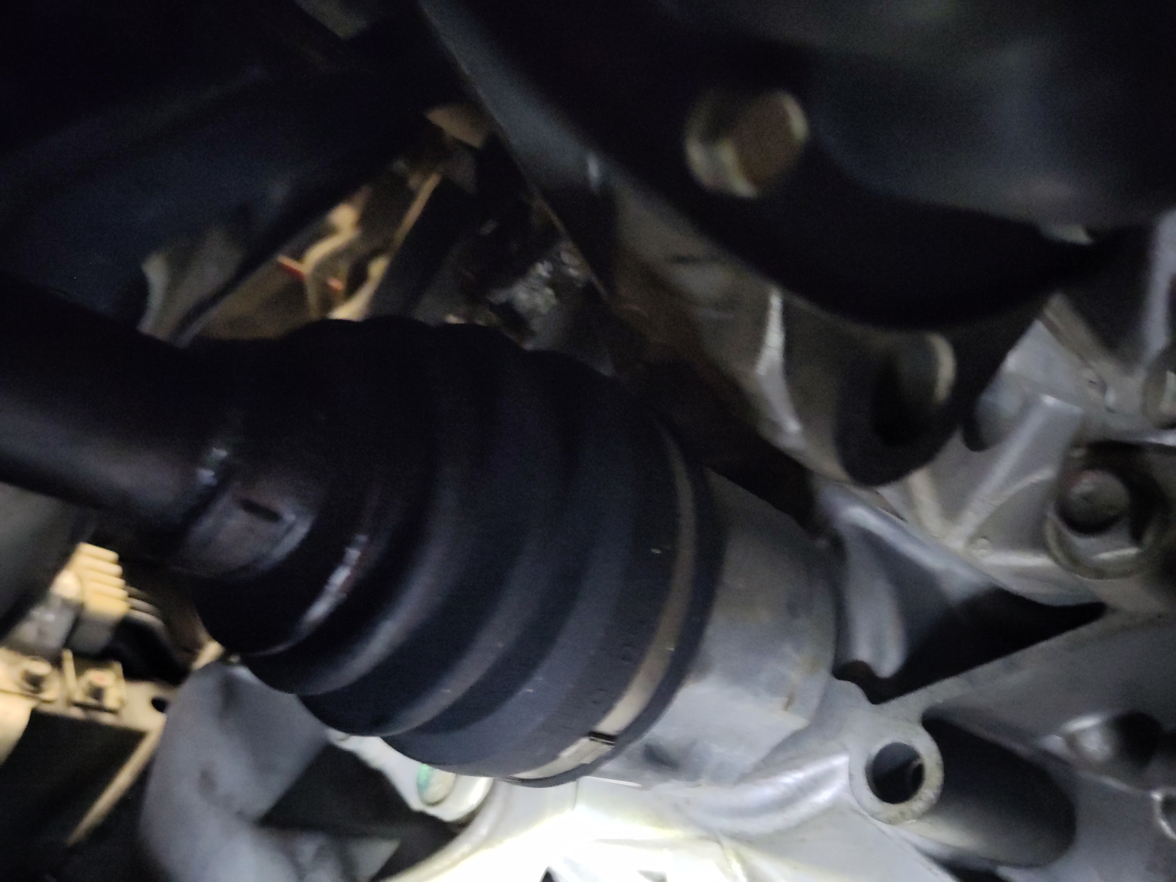
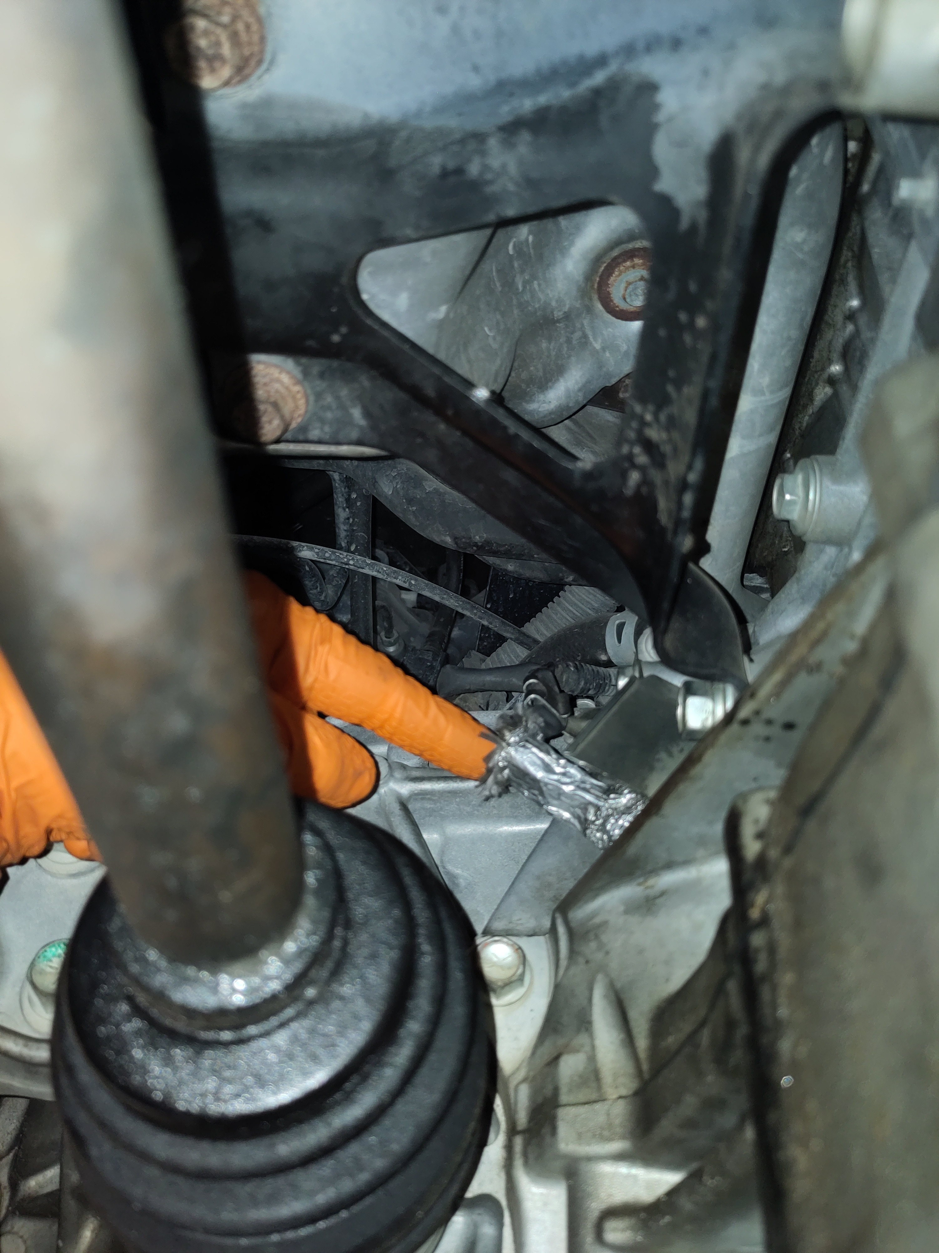
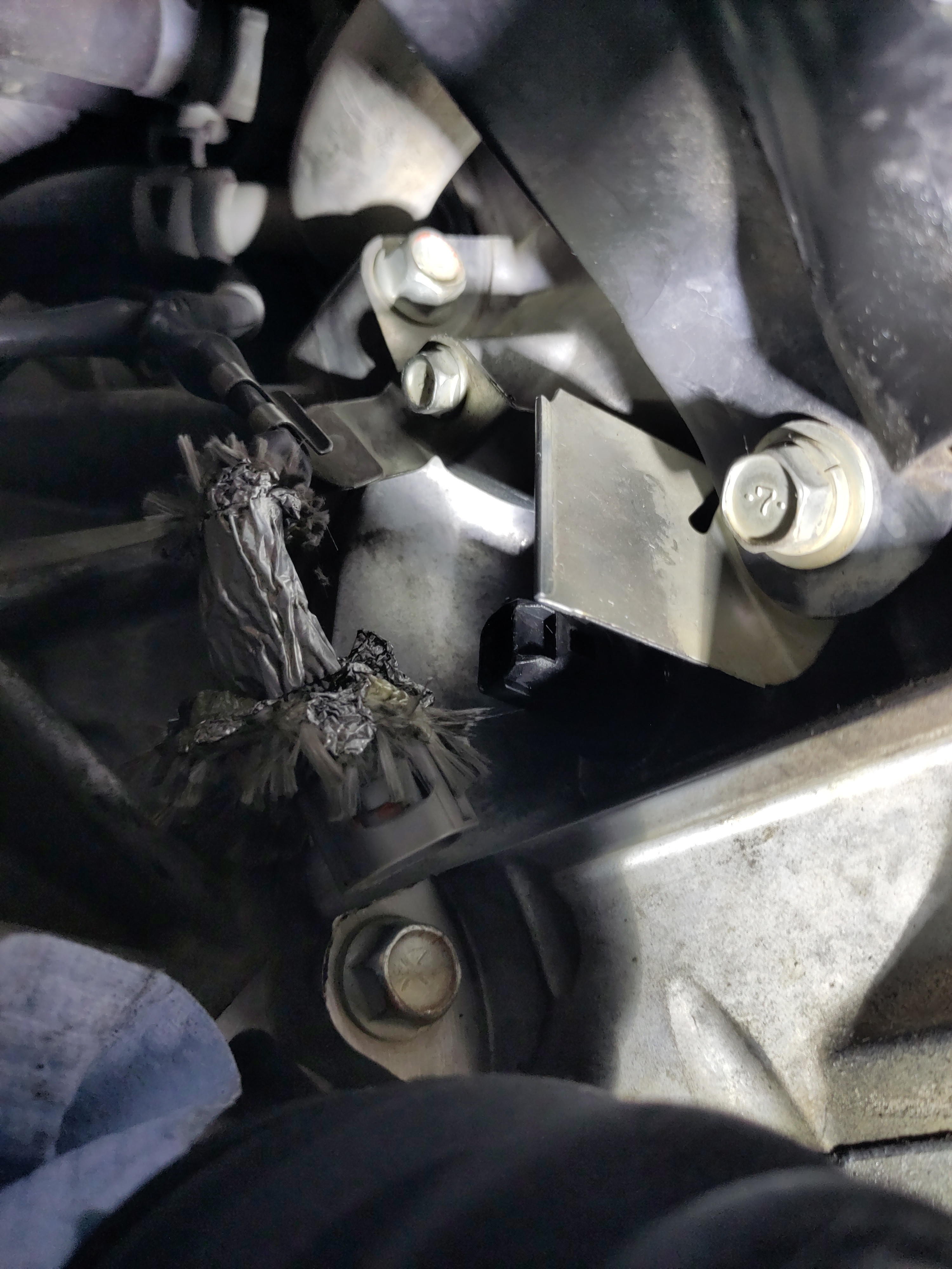
- You will need to remove the plastic covers from underneath the vehicle to gain access to the Crankshaft Position Sensor. The bolts are typically 10 mm in size, and there will also be several push or pull pins that must be removed. The sensor is located just above the CV axles. It is recommended to take photos of the bolt and pin locations before removal. Store all fasteners in a magnetic tray or another secure container so they are not lost during the process.
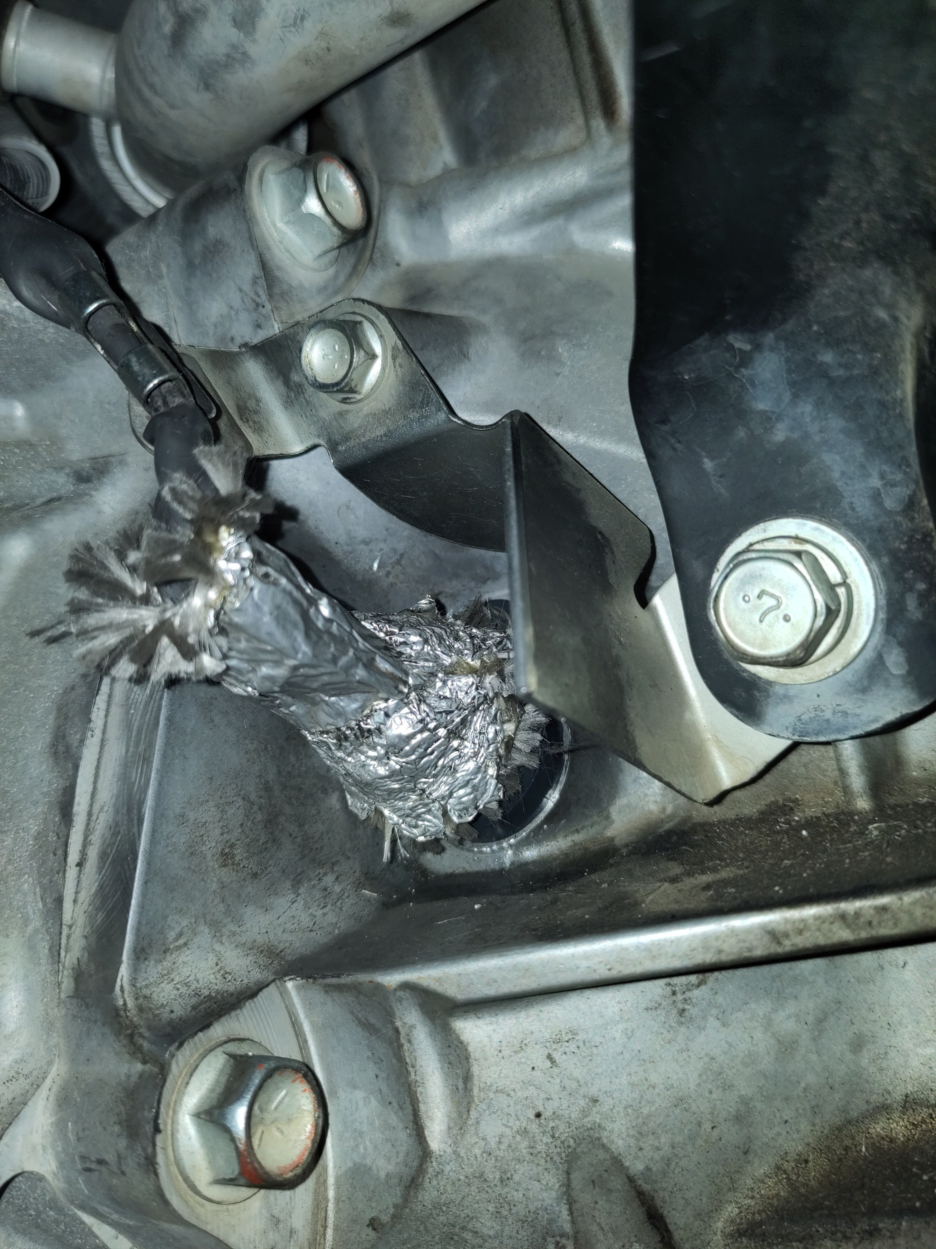
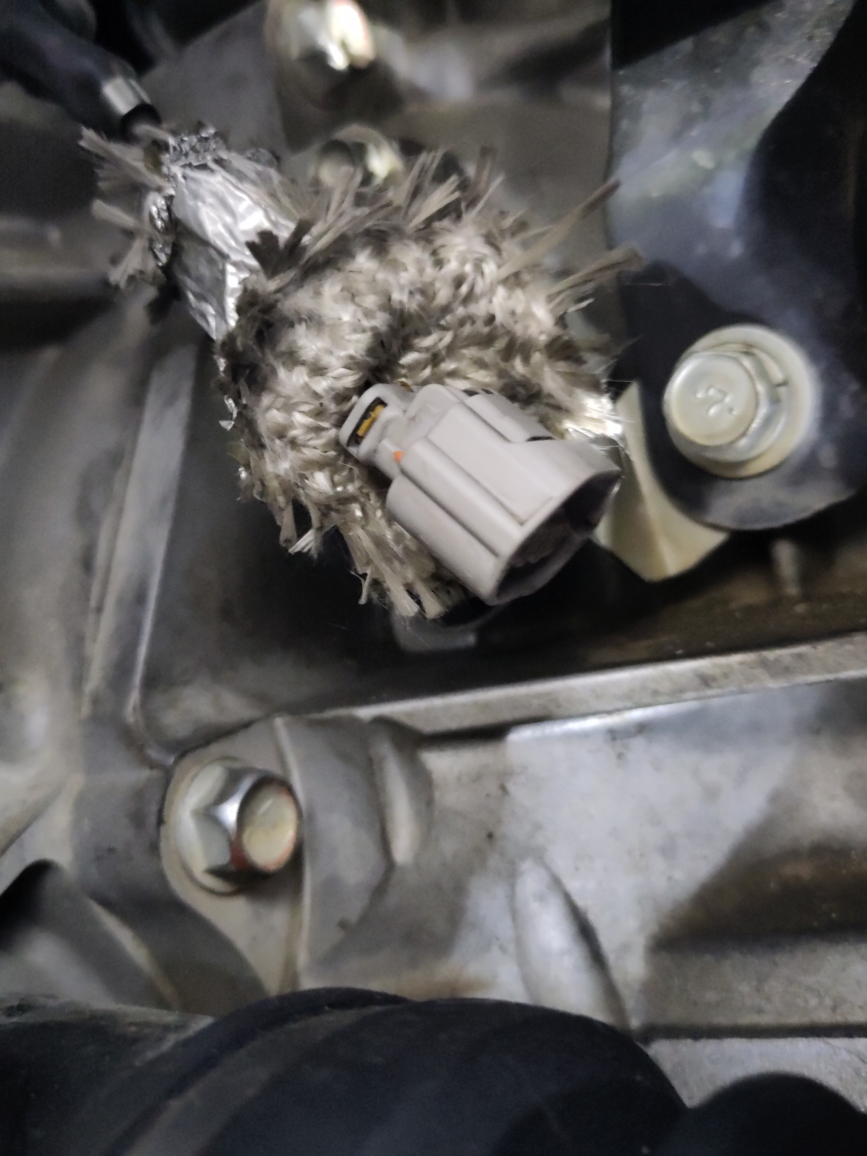
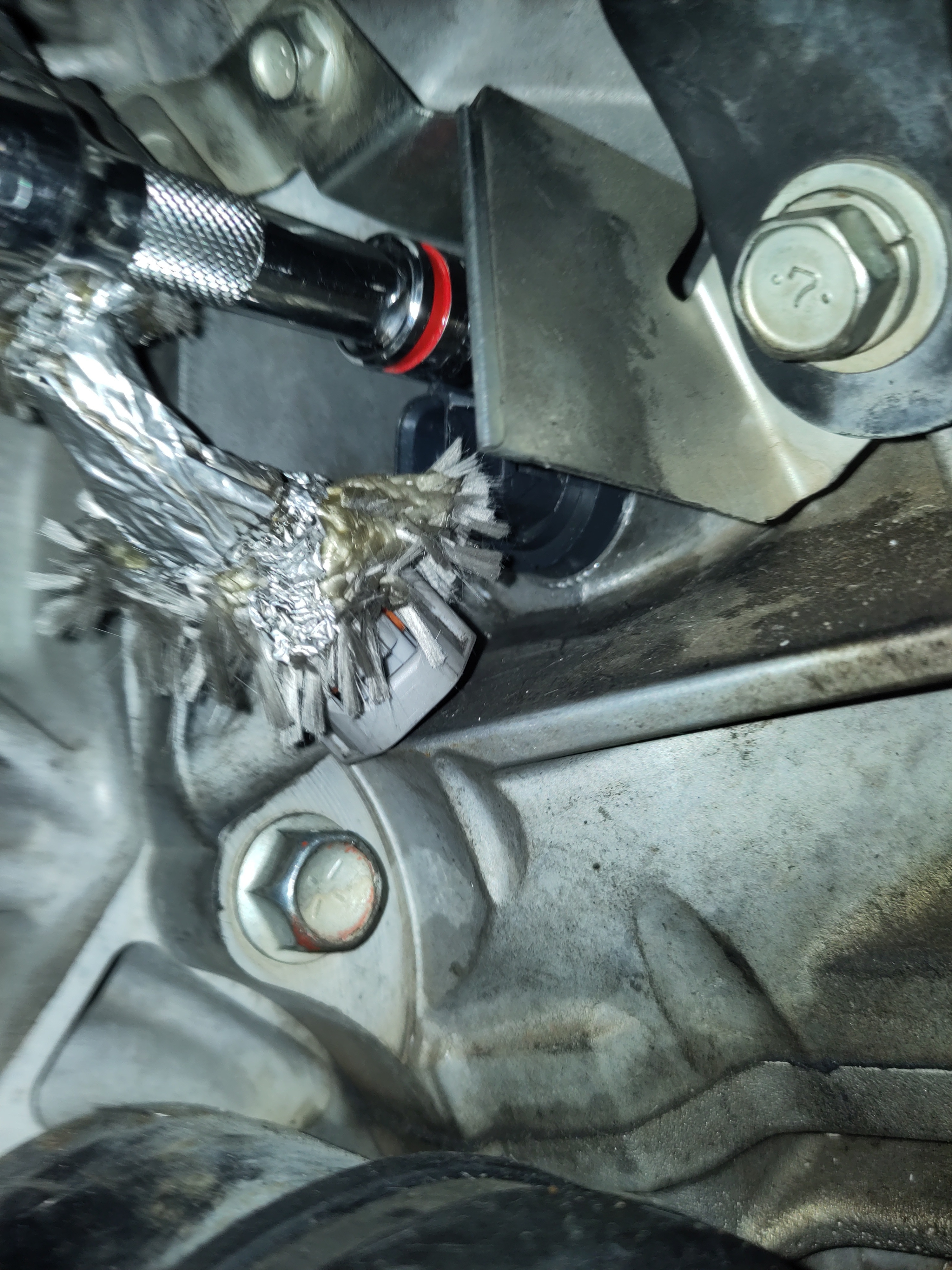
- Remove the electrical cover and pull out the electrical connection from the circuit.
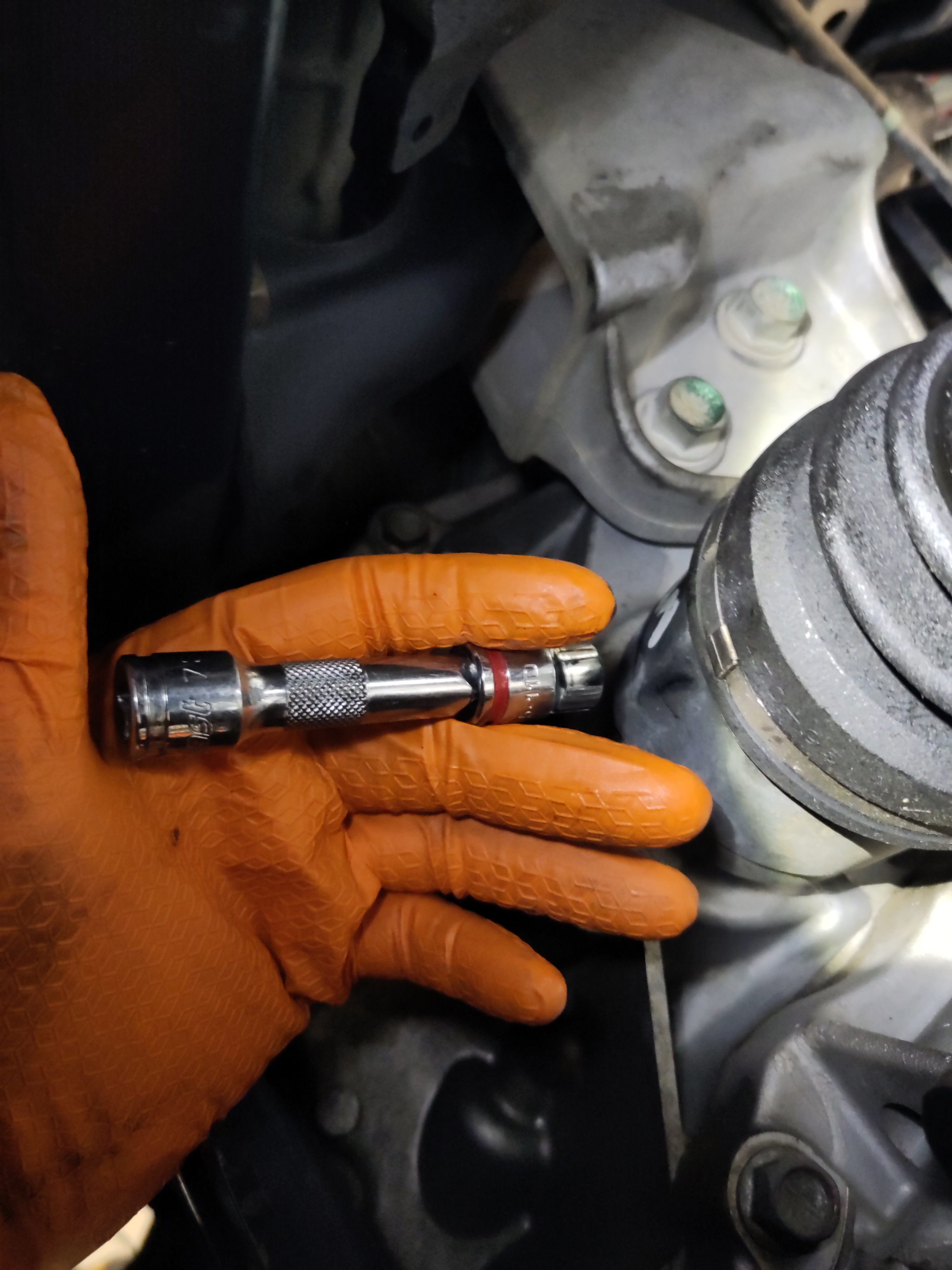
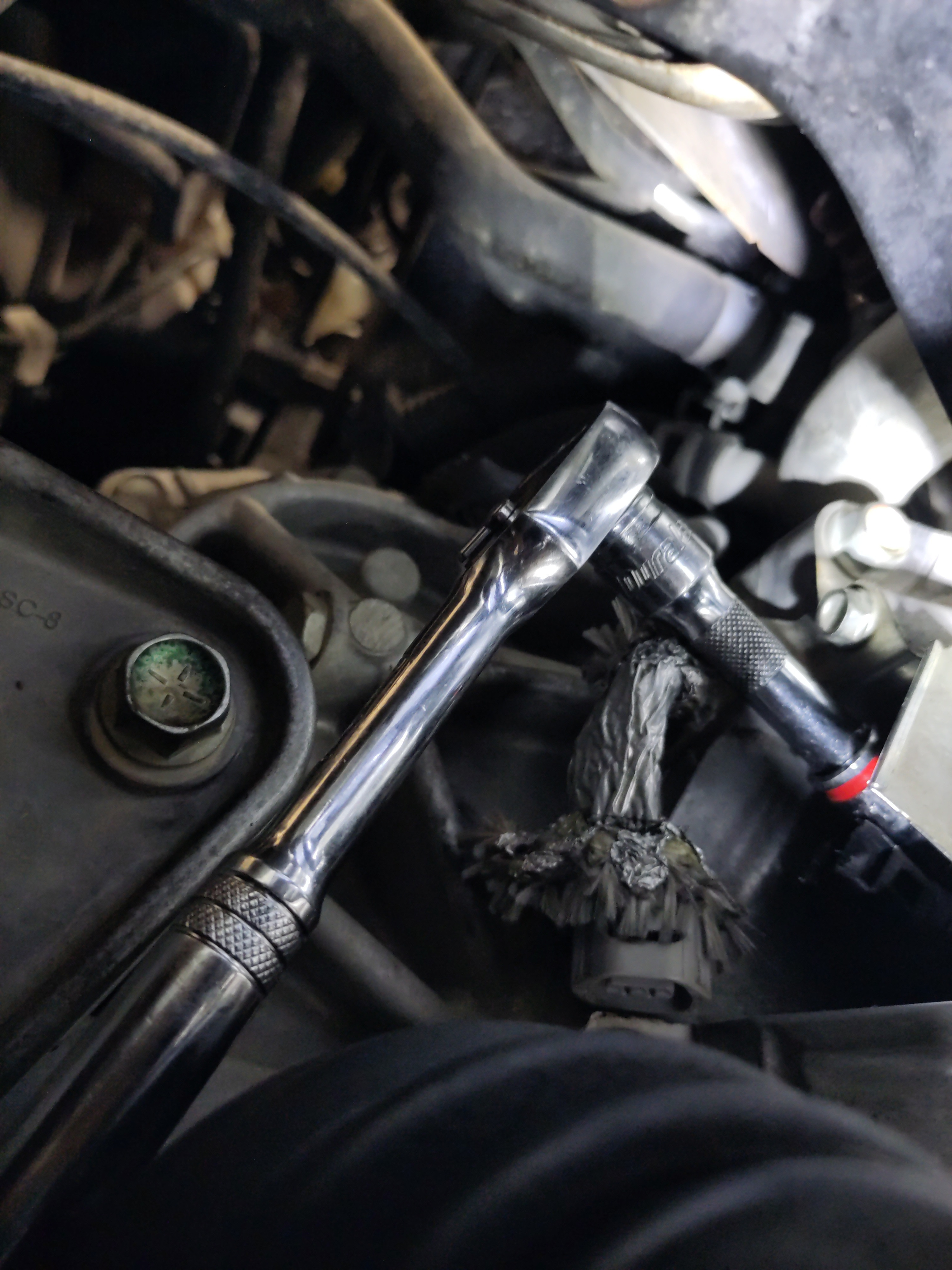
- Use the 12mm with the extension with the 3/8" drive to remove the bolt. Stash the bolt in a magnetic pan if possible to refrain from losing the bolt.
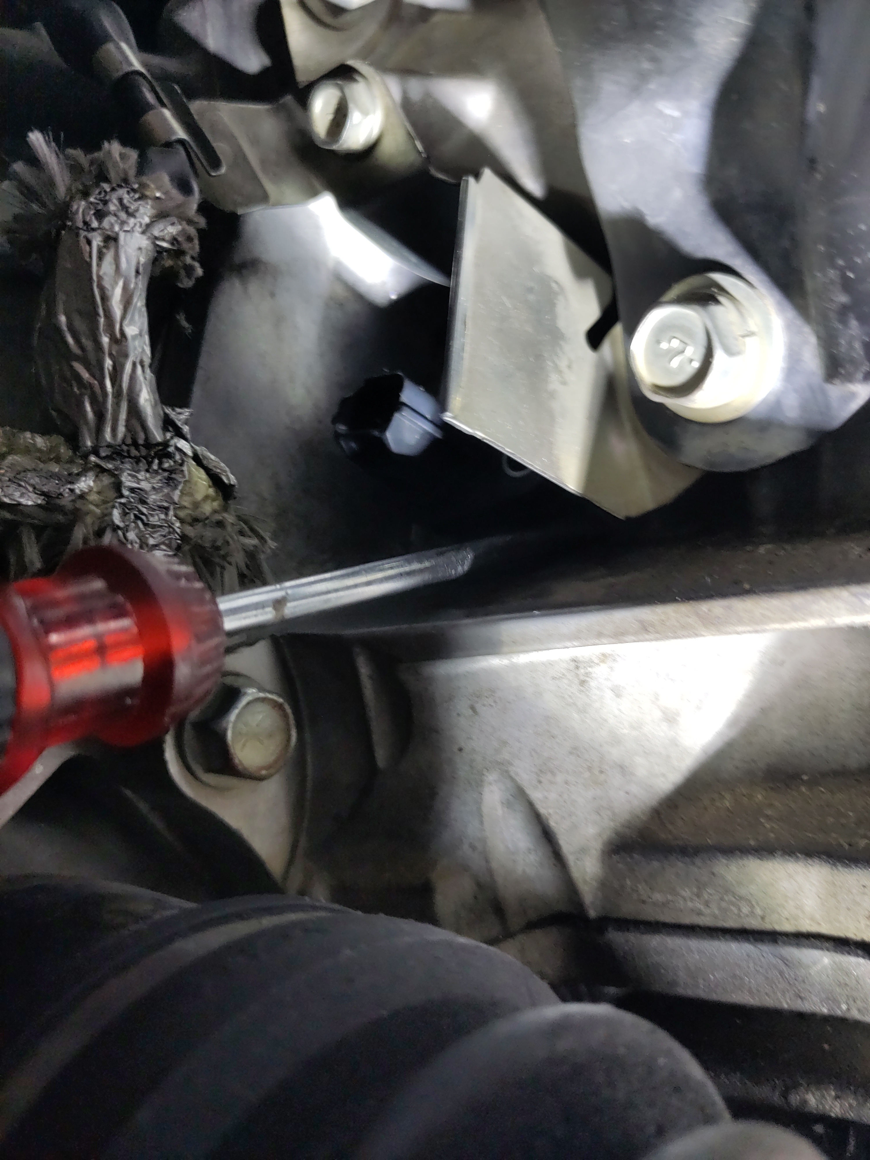
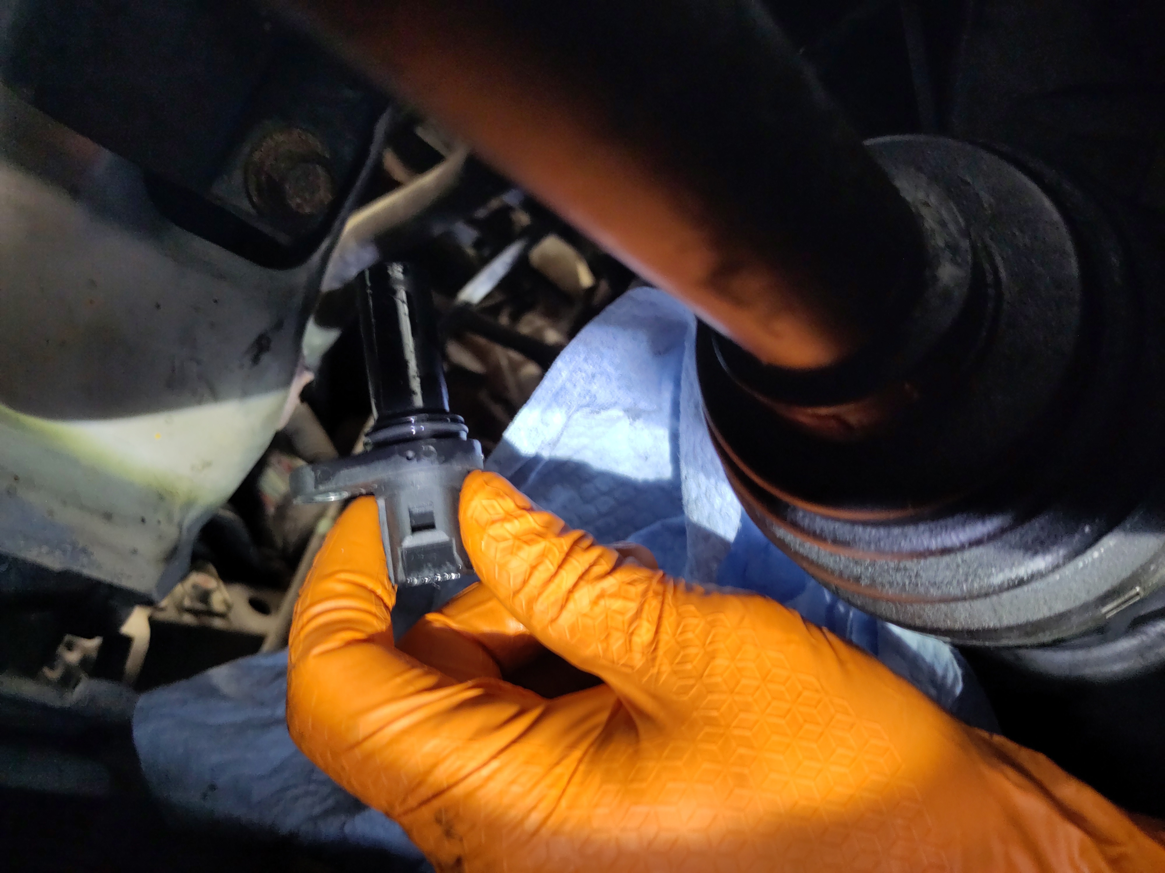
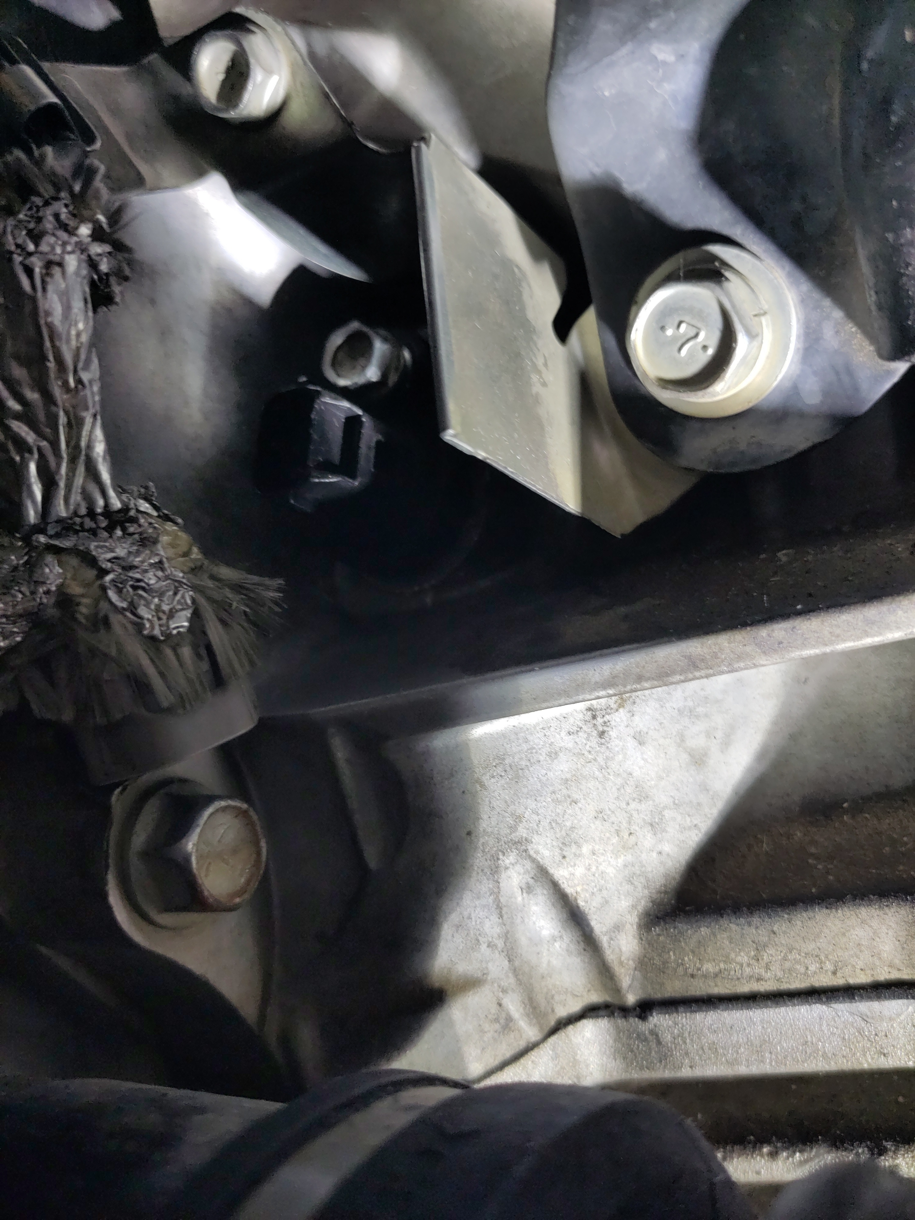
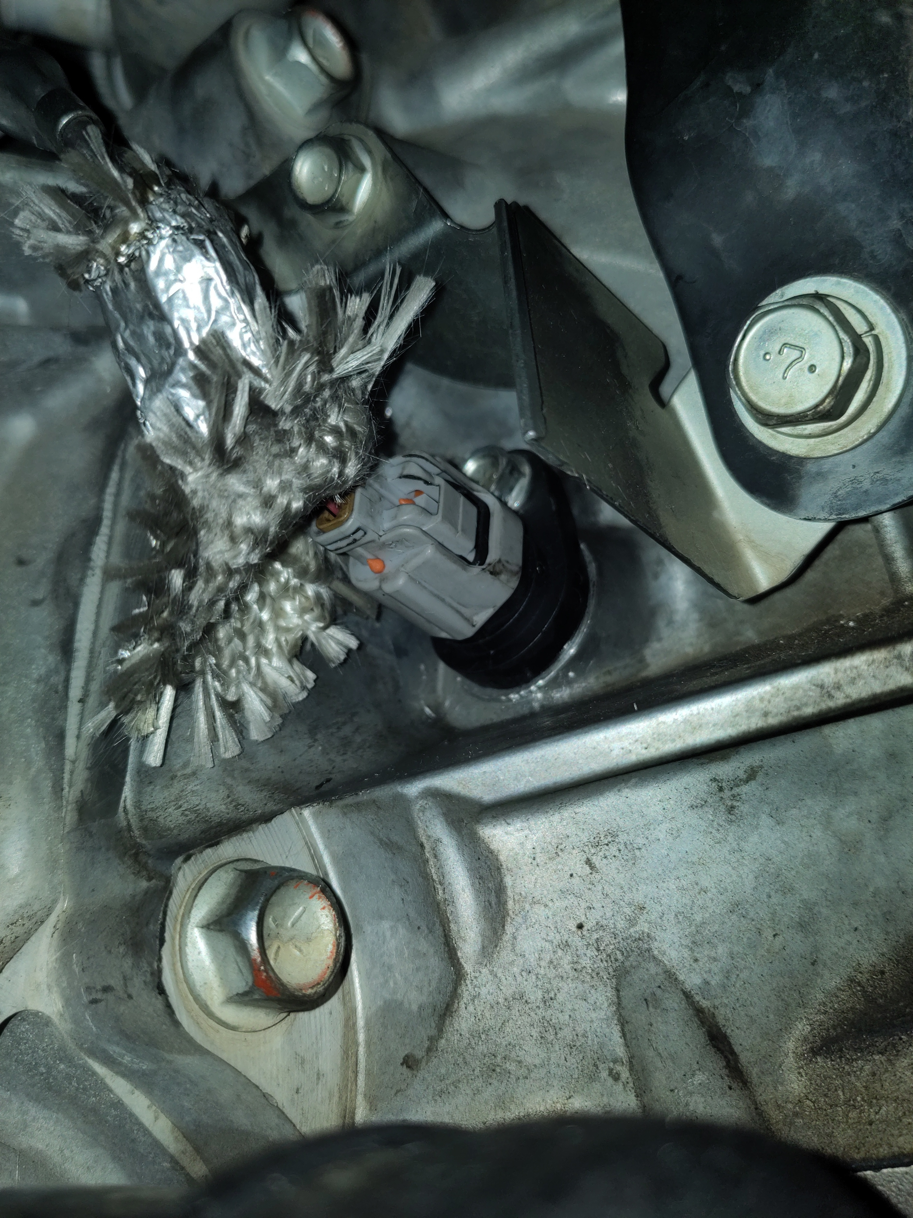
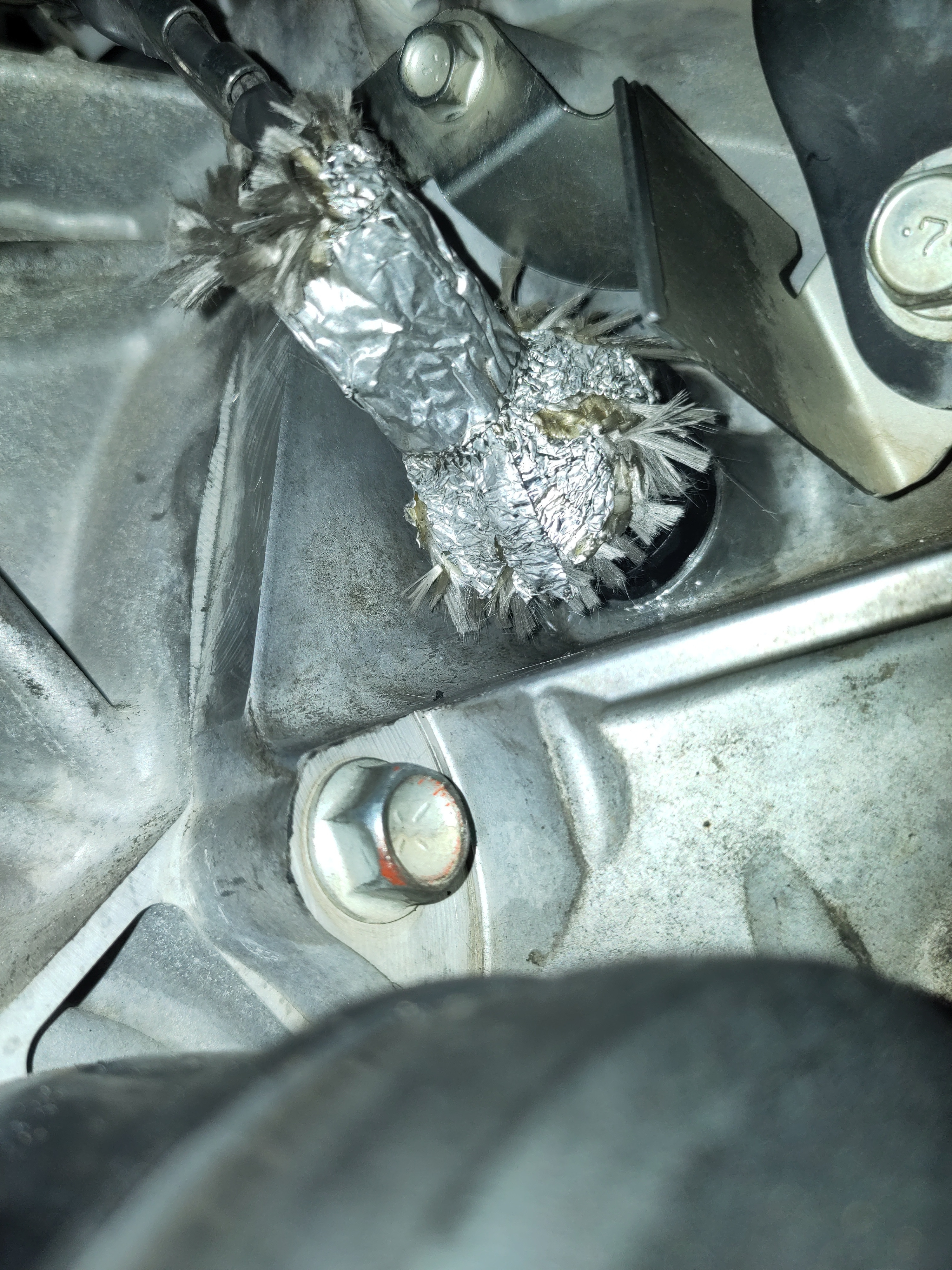
- The removal of the crankshaft position sensor could require some play. As in it may be beneficial to use your hand to rotate, wiggle while pulling up on the sensor. If necessitated, a flat head would be useful in prying up the sensor. It does have an o-ring and the connection may completely sealed to due a build up debris. Once it is freed up, don’t remove it completely. Keep it in the hole until the new crankshaft positioning sensor it ready to be installed.


Preparation & Installation:
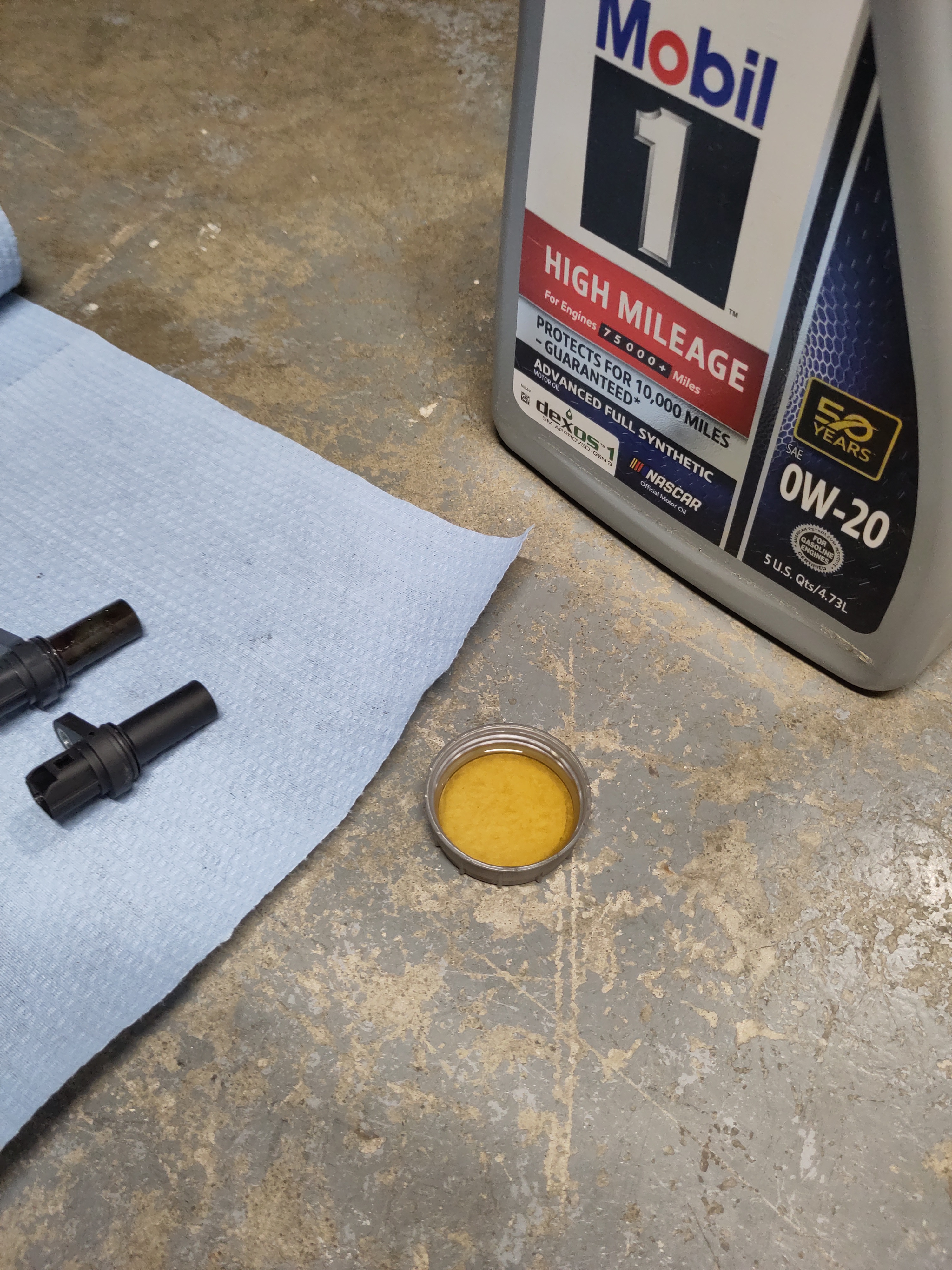
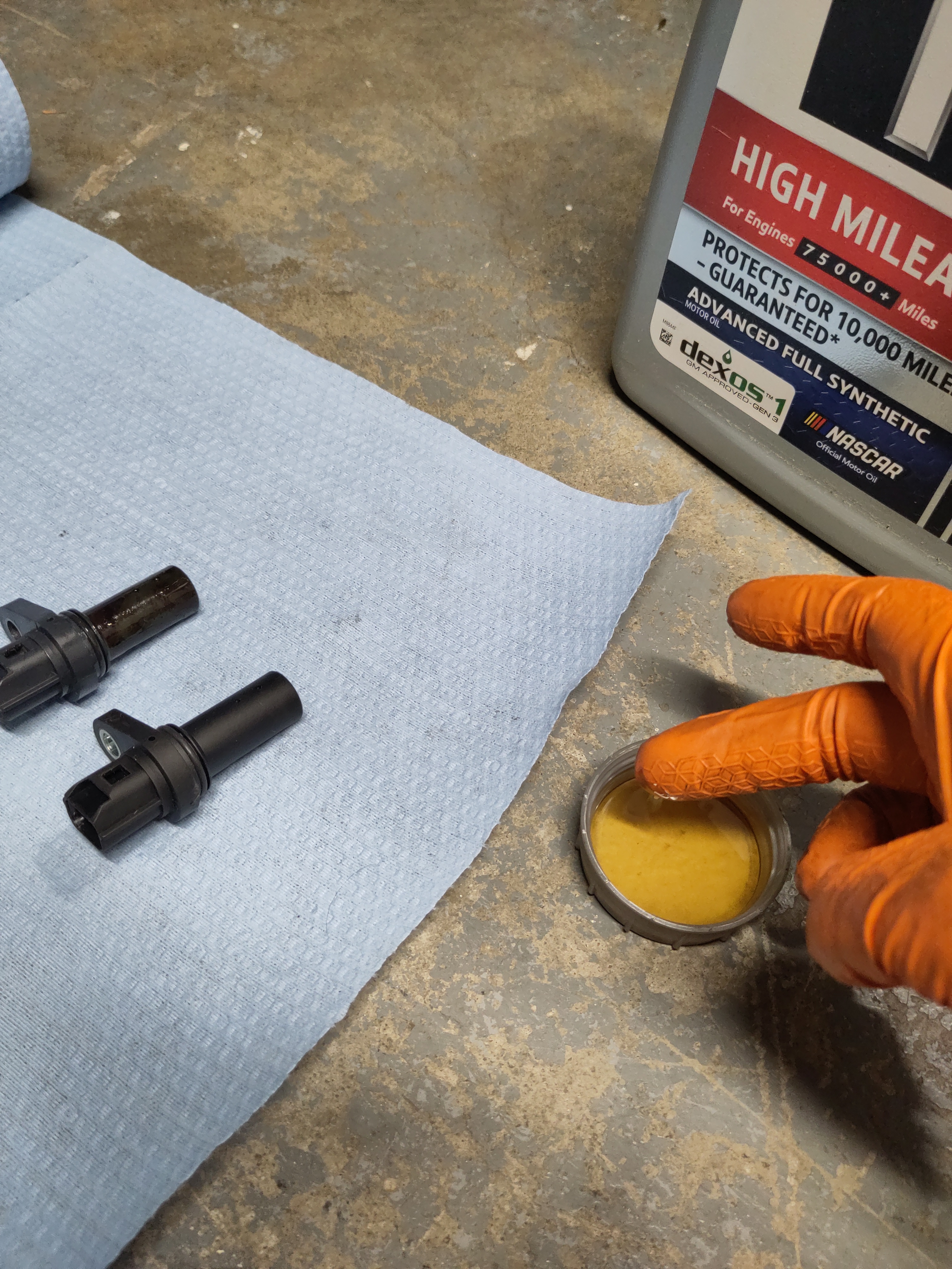
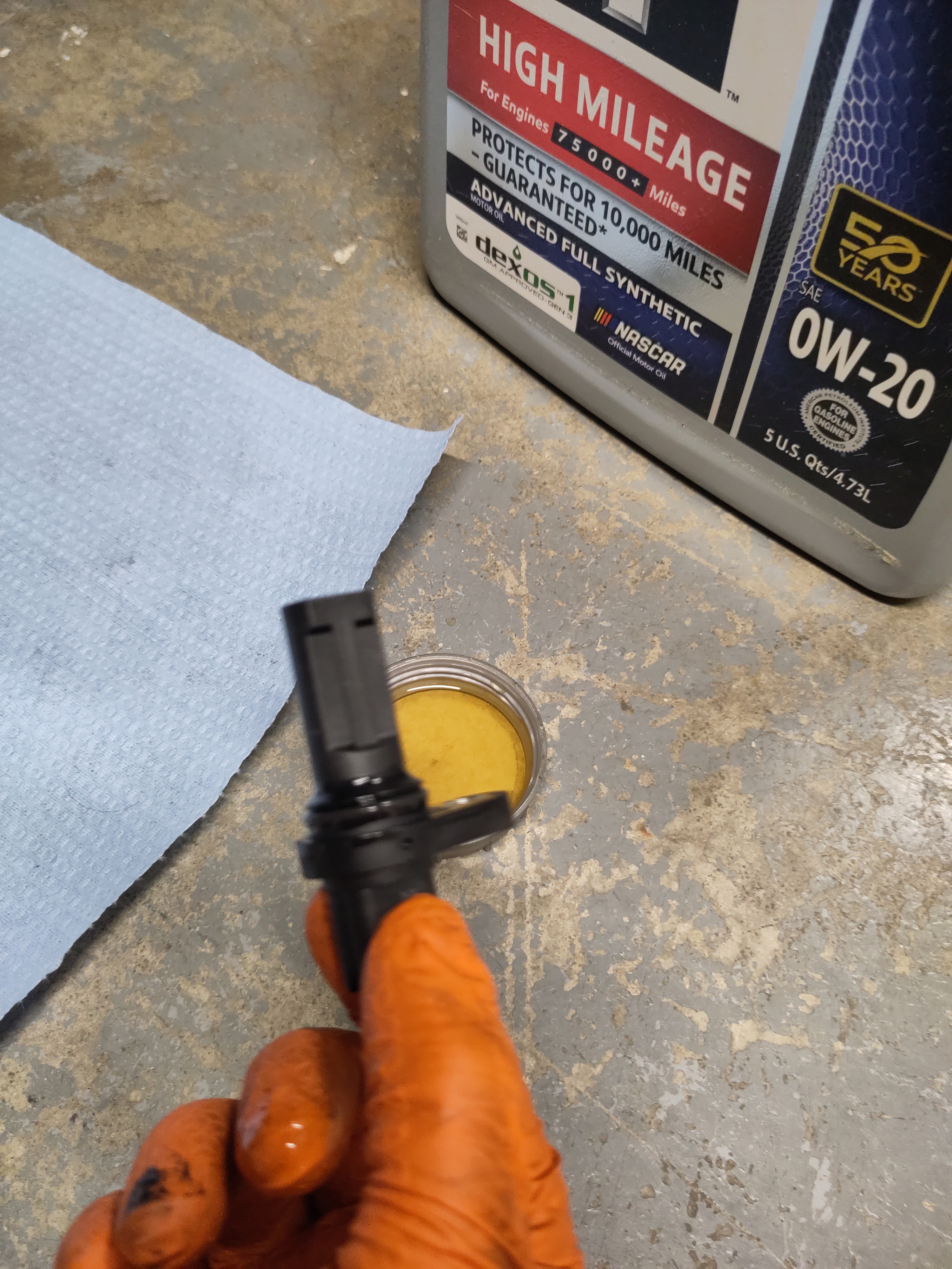
- Using the 0w-20 Engine Oil, pour small portion into the lid. Dip a Q-tip or your finger into the oil and lubricate the O-ring with the oil.
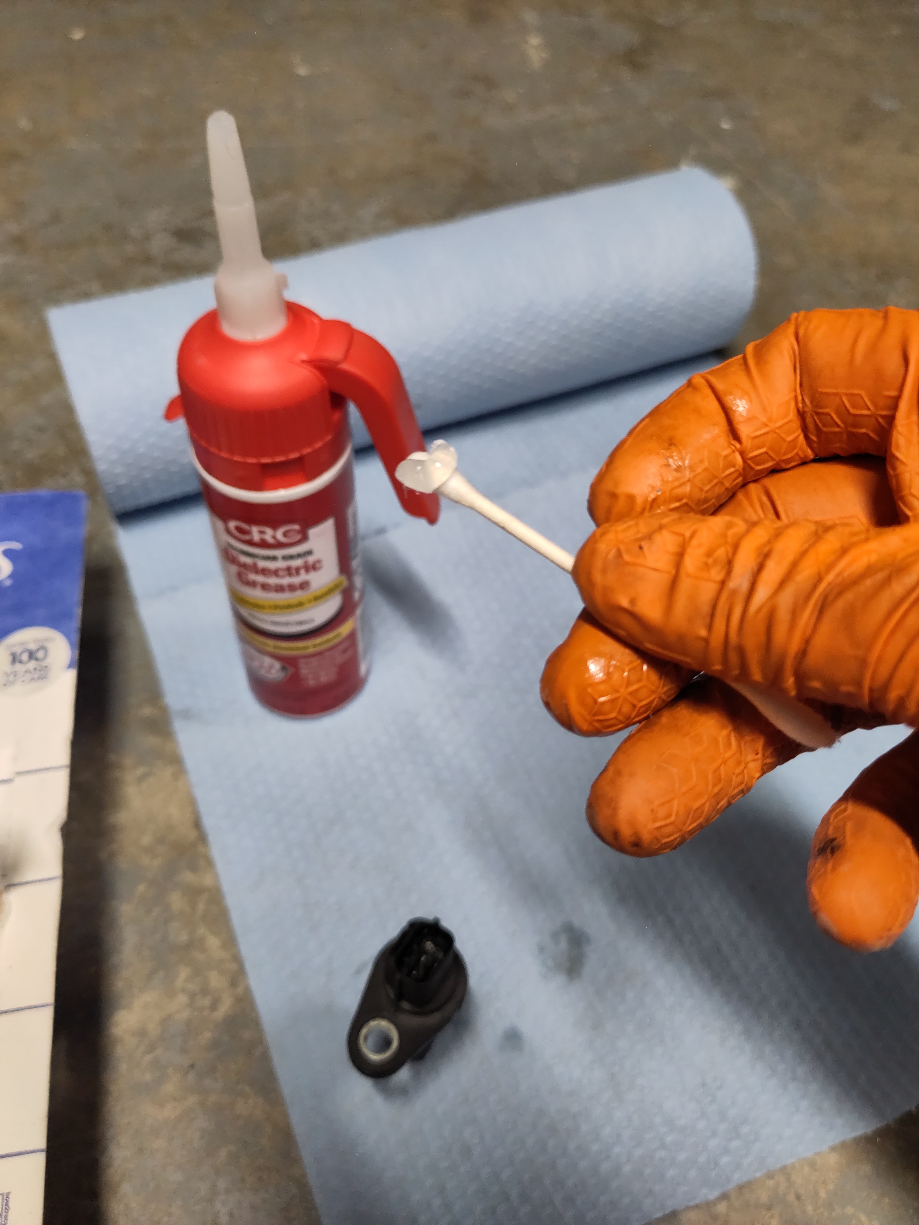
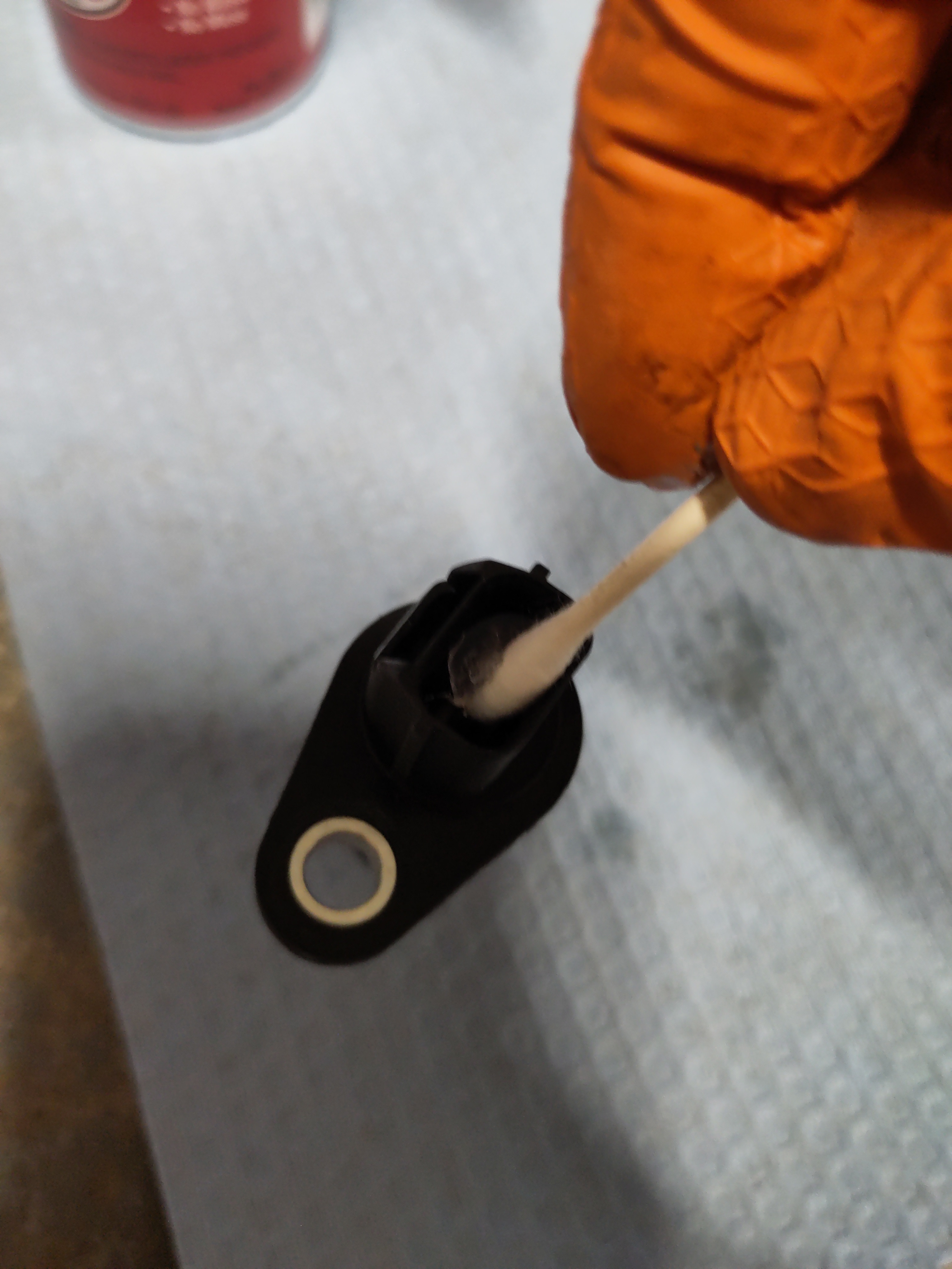
- Using the Dielectric Grease and a Q-tip, apply the grease to the three pins of the sensor in order to mitigate corrosion down the road.
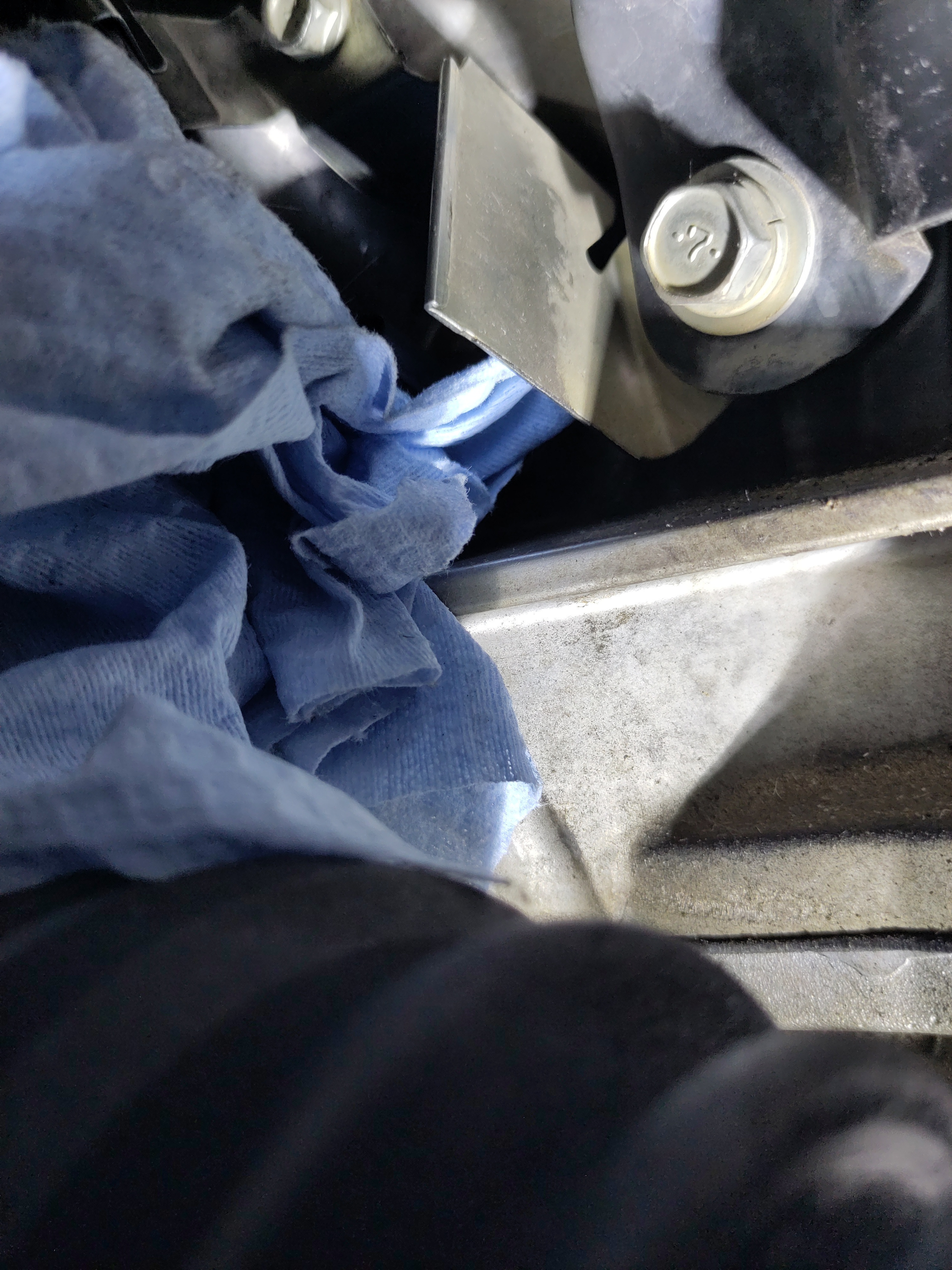
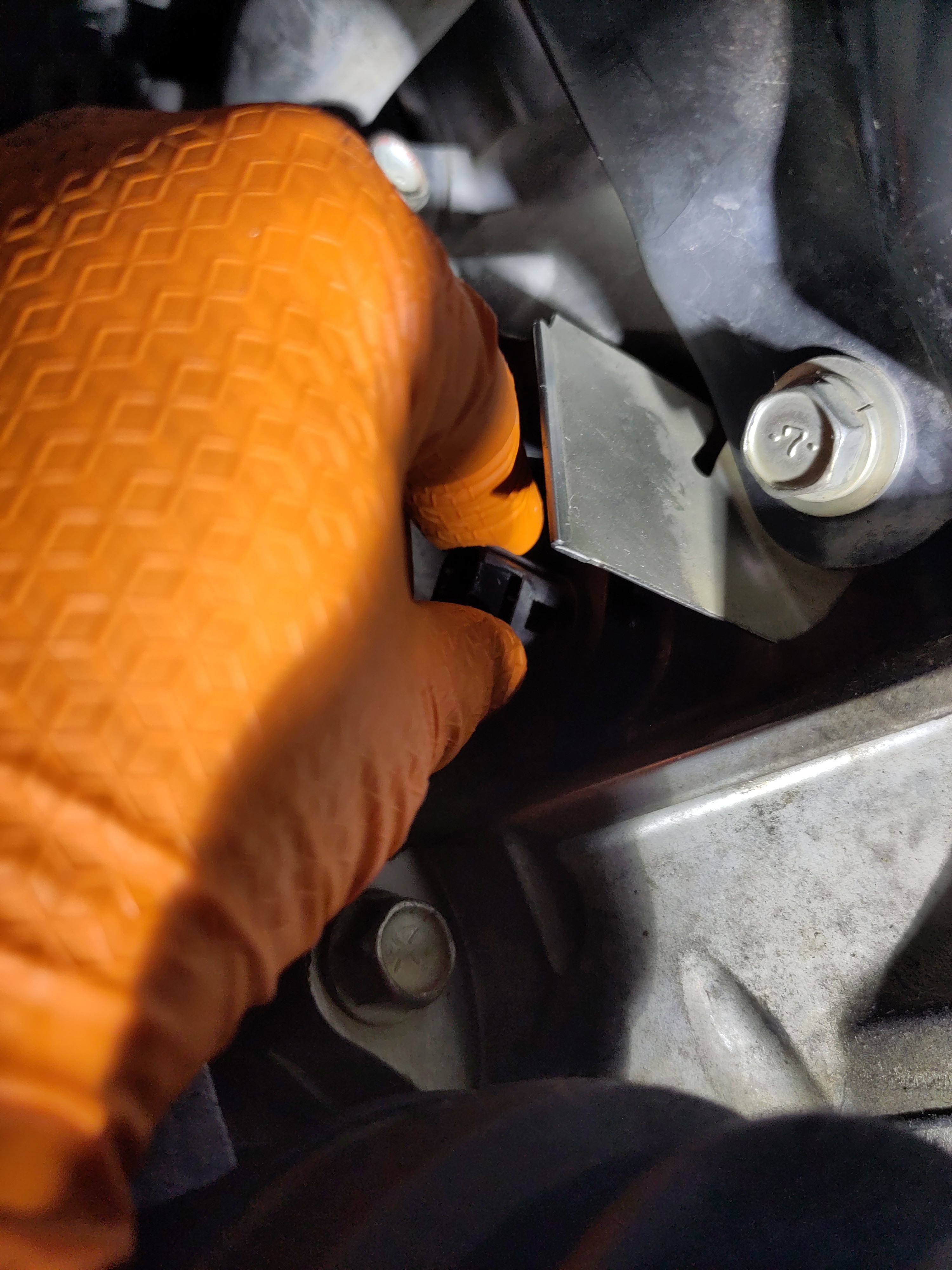
- Now get under the vehicle with the new sensor. Remove the old sensor, and wipe down the surrounding area. I found it easy to install the sensor wiggling it in there. I had the placement of the bolt hole of the sensor pointed to the right when in the engine hole then I rotated 90 degrees upwards to align the hole with the bolt hole.
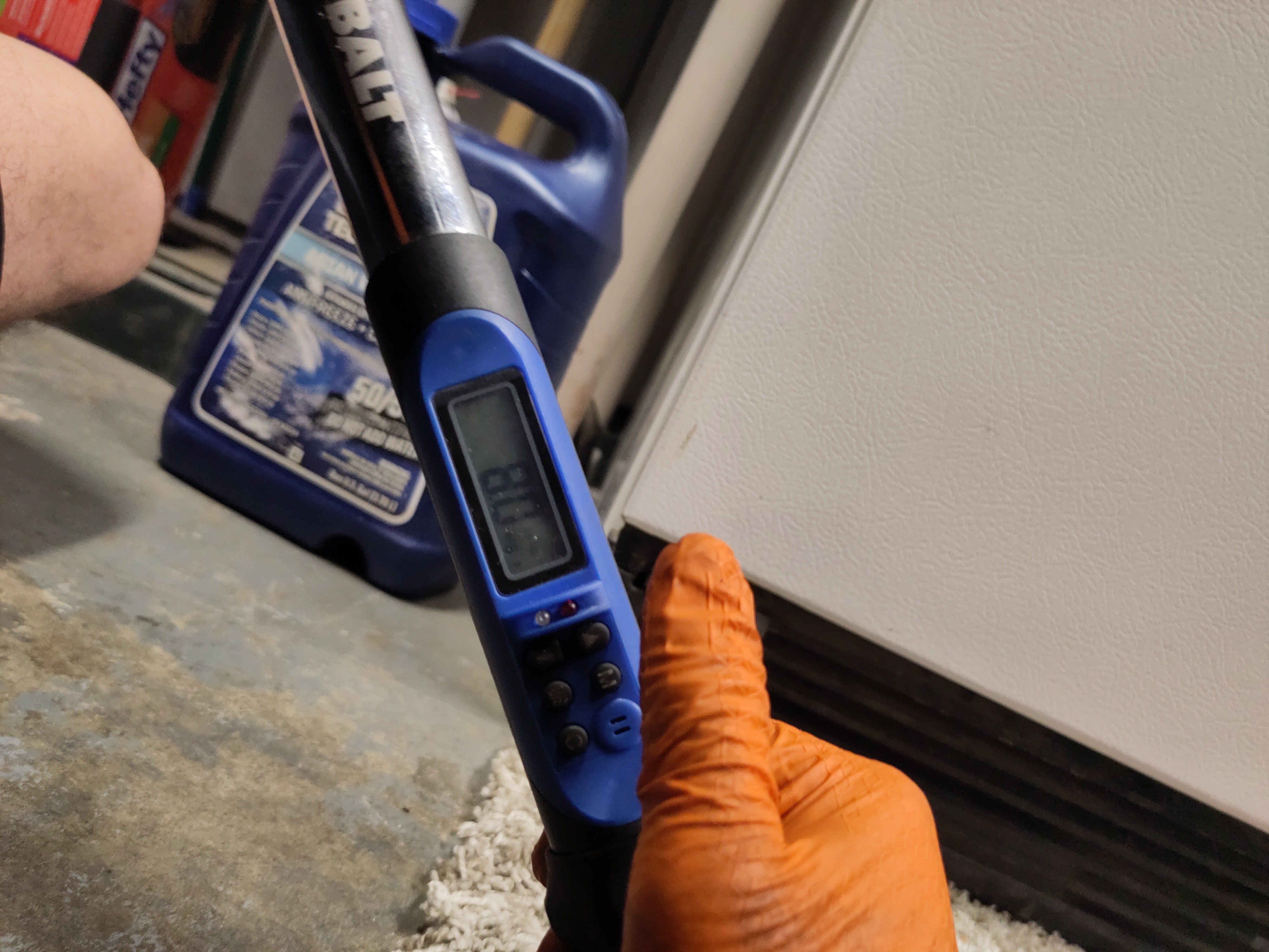
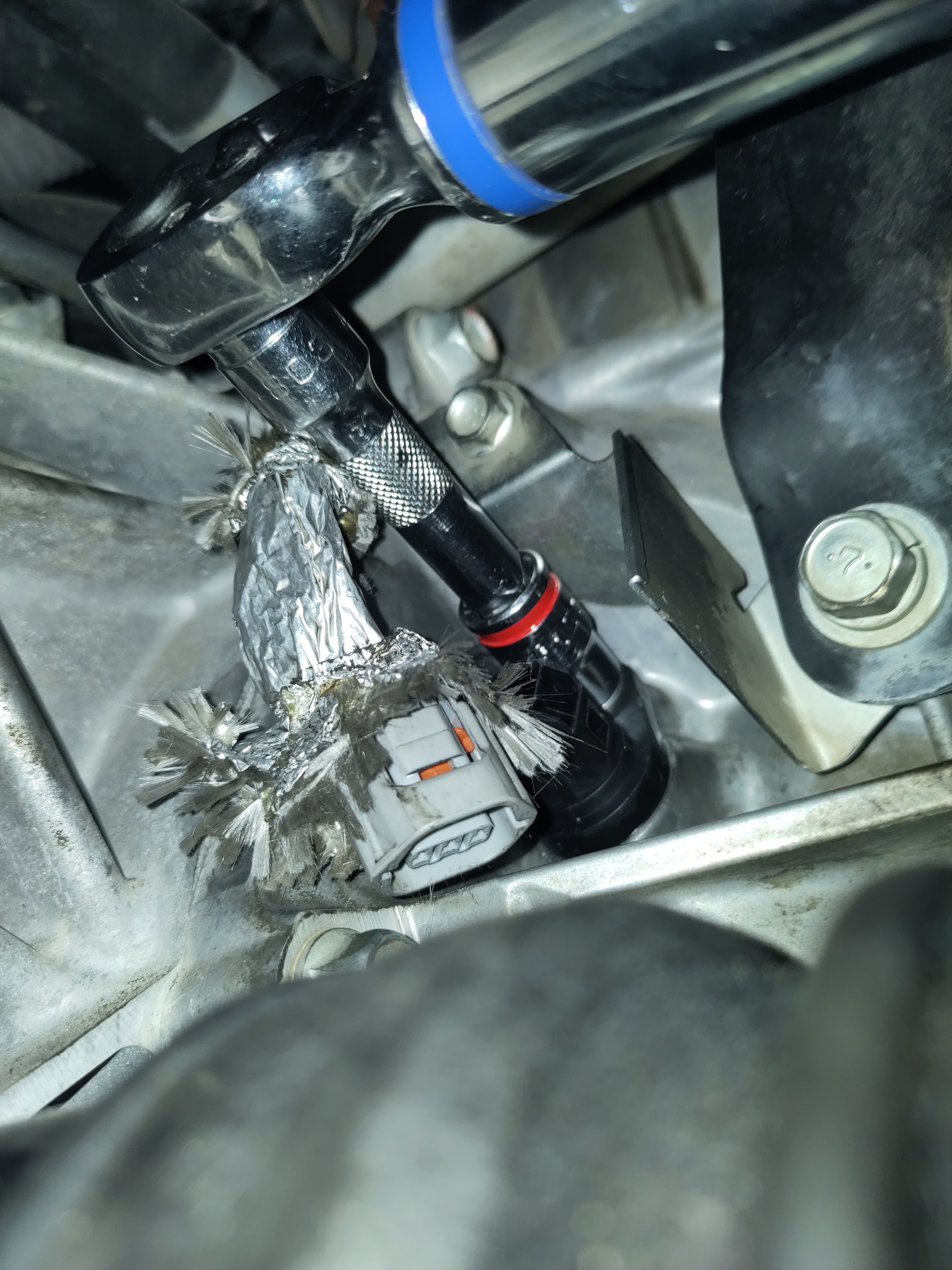
- Next, hand tight the 12mm bolt initially. Use the 3/8" wrench with extension to tighten it down the rest of the way. Using the 3/8" torque wrench, torque the bolt down to 8 ft-lbs.
- Before reconnecting the electrical connection to the sensor. Make sure the cover is on wrinkled up, but it is flaring out and can be properly seated so it can keep the electrical connection and the surrounding area dry. Connect the electrical connection. There will be an audible clicking sound verifying a solid connection. Ensure the cover is properly seated, and compress with your hand to ensure to takes form the electrical connection and the sensor.
- Secure the Plastic shields and install any necessary bolts and plastic pins. Refer to your photos as necessary.
- Re-connect the ground cable to the negative battery terminal.
- Put the vehicle back on the ground.
Testing and Trouble Shooting Sensors:
It is possible to test whether the Crankshaft Position Sensor is functioning correctly by identifying its electrical pins and using a multimeter to perform a basic test. By connecting the multimeter to the power and ground pins, you can check for voltage output while moving a metallic or magnetic object in front of the sensor, since the sensor generates voltage through its internal magnetic field interaction. If a voltage reading is present, the sensor is likely operating correctly, but if no reading appears, it may be faulty or malfunctioning. The electrical schematic referenced was found on an EVO forum and helps identify the pin layout and circuitry, and further troubleshooting steps will be added to this tutorial over time. For additional guidance, refer to the provided references, which include more information for diagnosing and replacing the sensor on the 2013 Mitsubishi Lancer.
References:
- Crankshaft Positioning Sensor functionalityhttps://autorepairszone.com/crankshaft-position-sensor/
- Wiring Diagramhttps://www.evolutionm.net/forums/lancer-how-tos-installations/707399-ckp-sensor-tests.html
- Video TutorialVideo tutorial: https://www.youtube.com/watch?v=xuIHkCnkY7c