Last Updated: 05-10-2026
Vehicle: 2013 Mitsubishi Lancer ES
Testing an Electromagnetic Relay
Introduction:
Over time, vehicles have evolved from purely mechanical systems into increasingly complex machines with integrated electrical and electronic components. The purpose of introducing electrical systems was to automate processes, improve control, and enable diagnostic capabilities for identifying mechanical and electrical faults. When a vehicle is started by turning the ignition key, a series of automated electrical processes are initiated, including the operation of electromagnetic relays, which allow low-voltage control circuits to safely switch higher-voltage systems on and off. When the ignition is activated, multiple switches and relays engage in sequence to power essential systems required for engine startup and operation, and while the vehicle is running, these electrical components work together to manage power distribution and system functionality as needed.
Relay’s Purpose and Functionality:
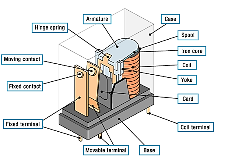
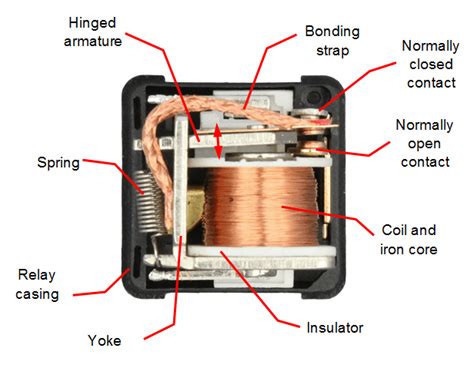
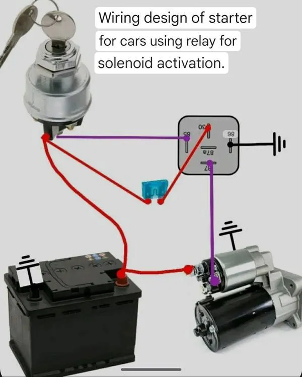
When the key is inserted into the ignition switch, it initializes the engine control module (ECM). The ECM can be associated of as the "brain" of the vehicle, responsible for governing, monitoring, and controlling the powertrain and its subsystems. Once the vehicle is powered on, the ECM takes priority in the startup sequence and begins coordinating system activation by sending control signals to various relays that power subsystems such as the fuel pump, starter motor, lighting systems, and other electrical components. These relays replace manual switching by using electromagnetism, where a low-voltage signal from the ECM energizes a coil inside the relay to generate a magnetic field that mechanically moves an internal switch between on and off positions, allowing a small electrical signal to safely control a much larger electrical load. The schematics below illustrate the internal operation of a relay and identify its key electrical and mechanical components.
Potential causes of failure:
The internal components of a relay may wear over time, or the coil and contact connections may become compromised. This can result from burned windings, carbon buildup, mechanical binding, contact welding, corrosion, or other forms of electrical and mechanical degradation. When these issues occur, the relay may fail to operate correctly or may intermittently lose connection, leading to electrical system malfunctions. Below are some common symptoms of a defective electromagnetic relay that may be observed in a vehicle.
- Vehicle wont start or unresponsive
- Engine light illumination
- Dead battery after night
- Engine Stalls
Tools & Components:
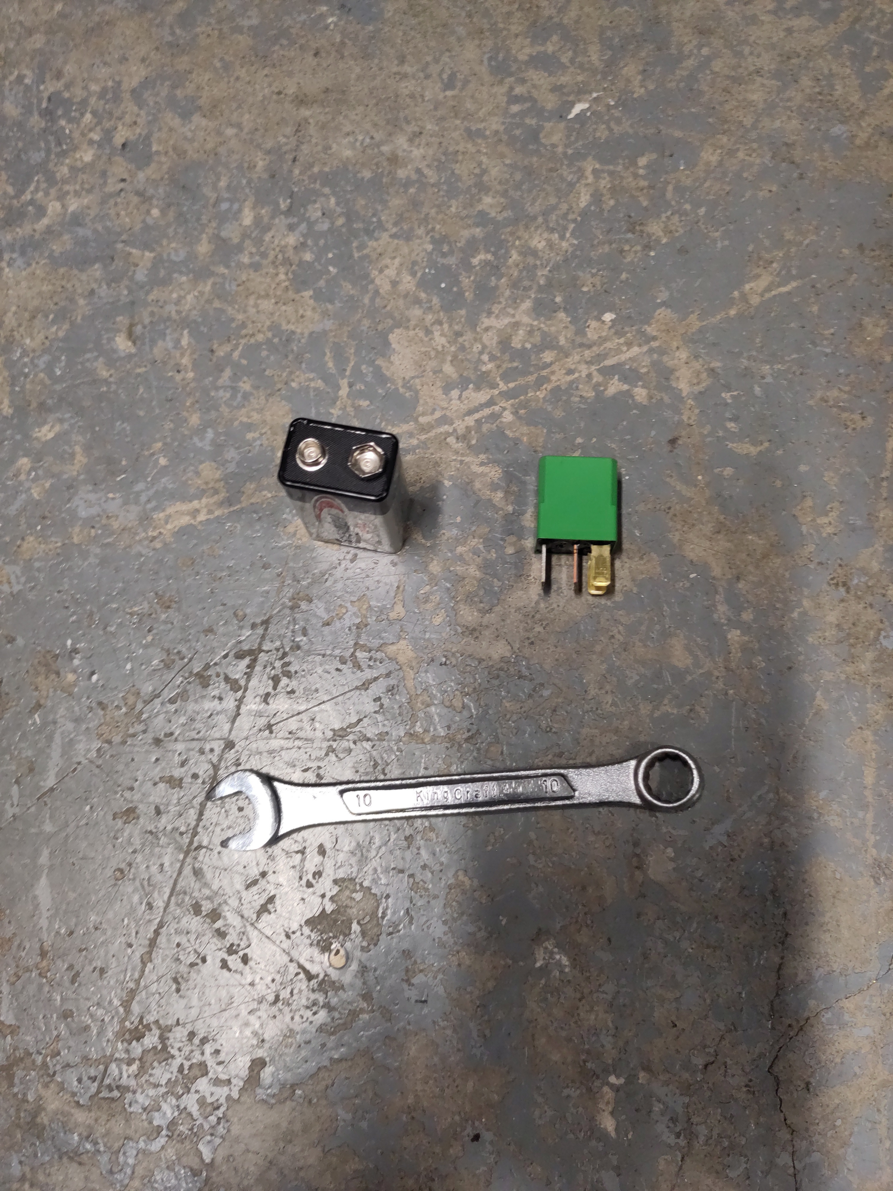
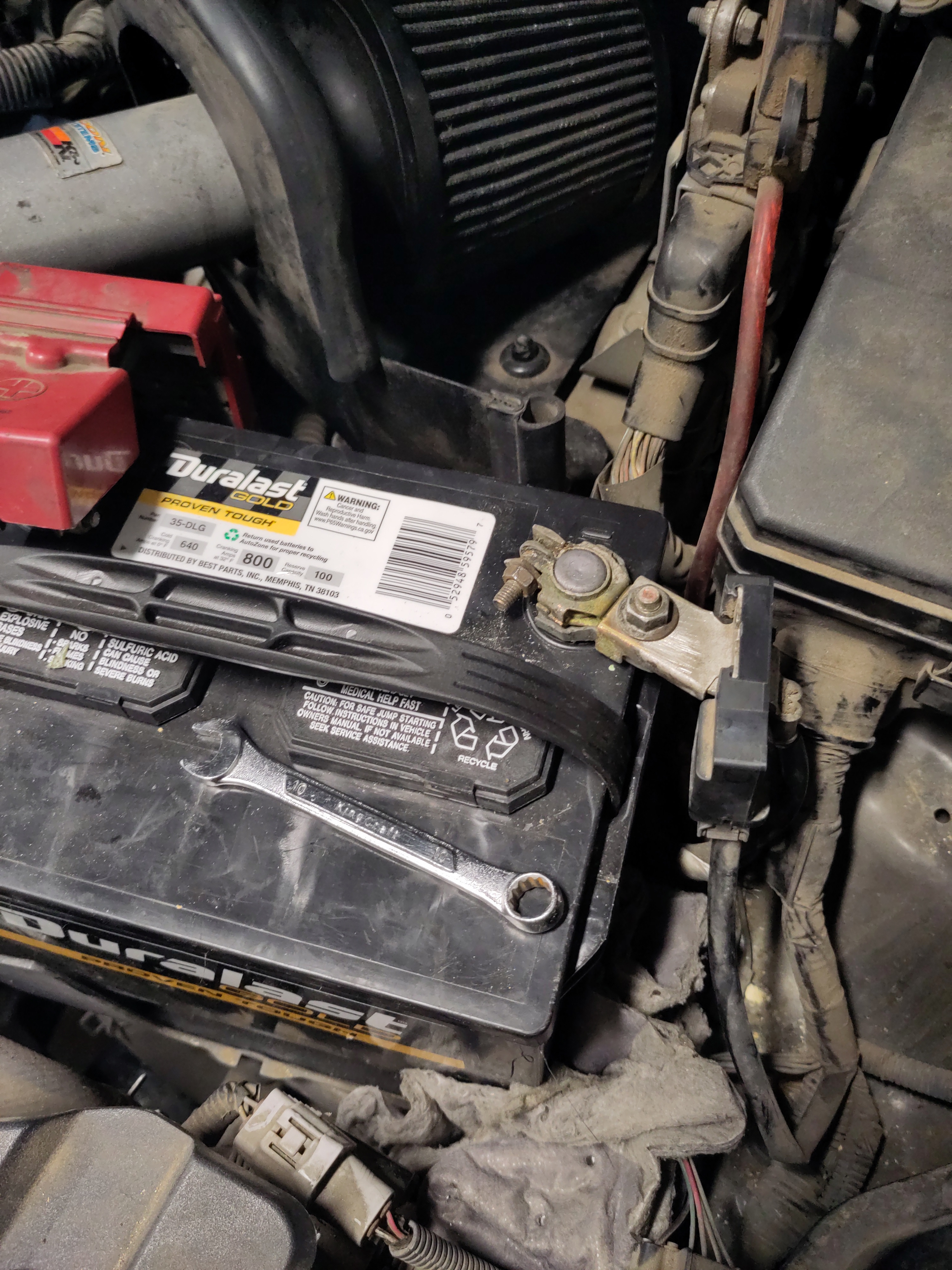
- 10mm wrench
- Electromagnetic Relay
- 9-Volt battery
Electromagnetic Relay location:
- Open up the hood of the vehicle.
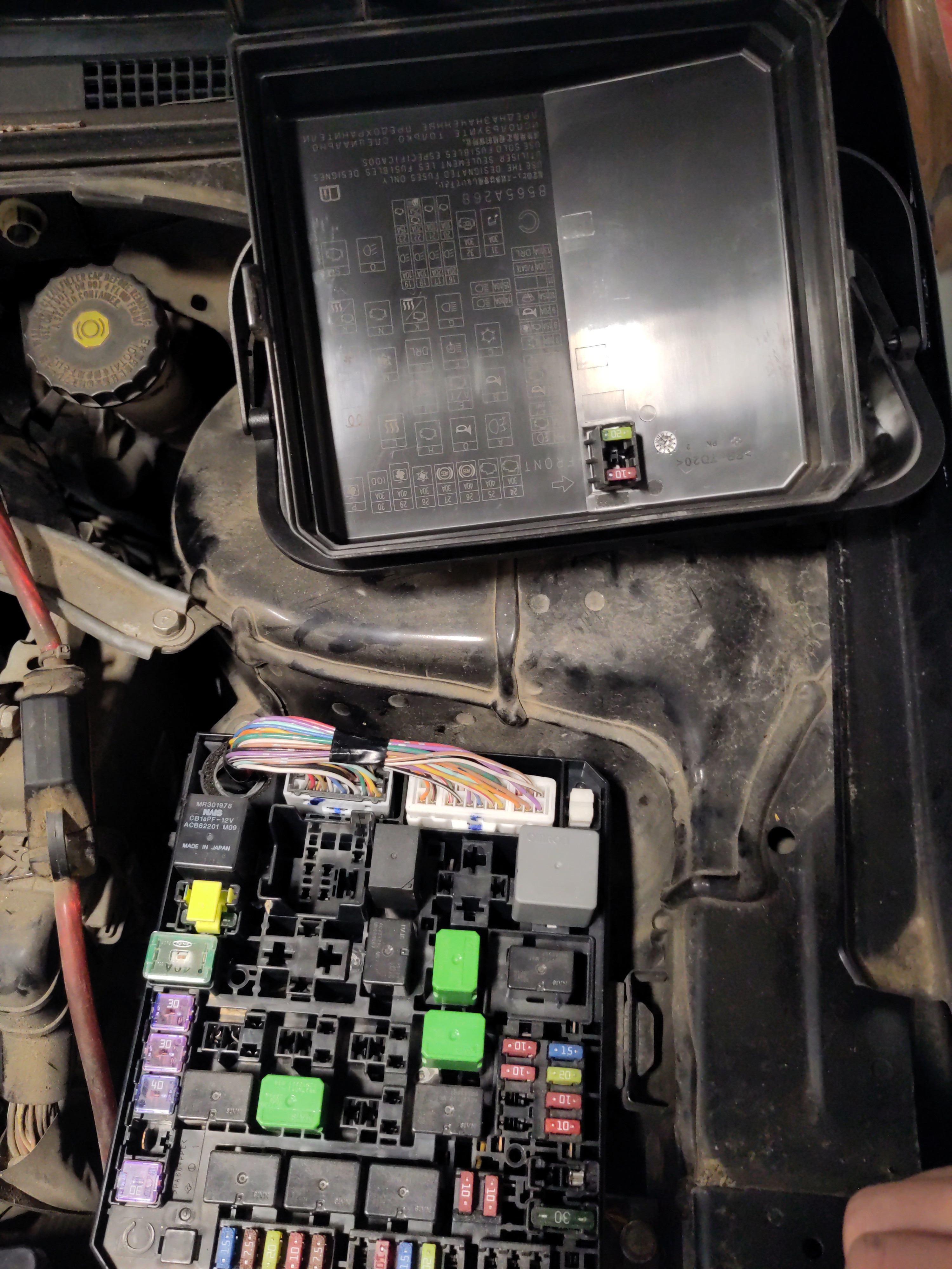
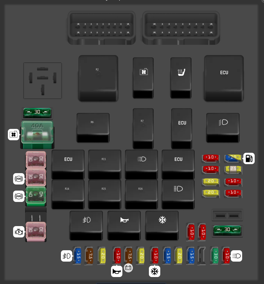
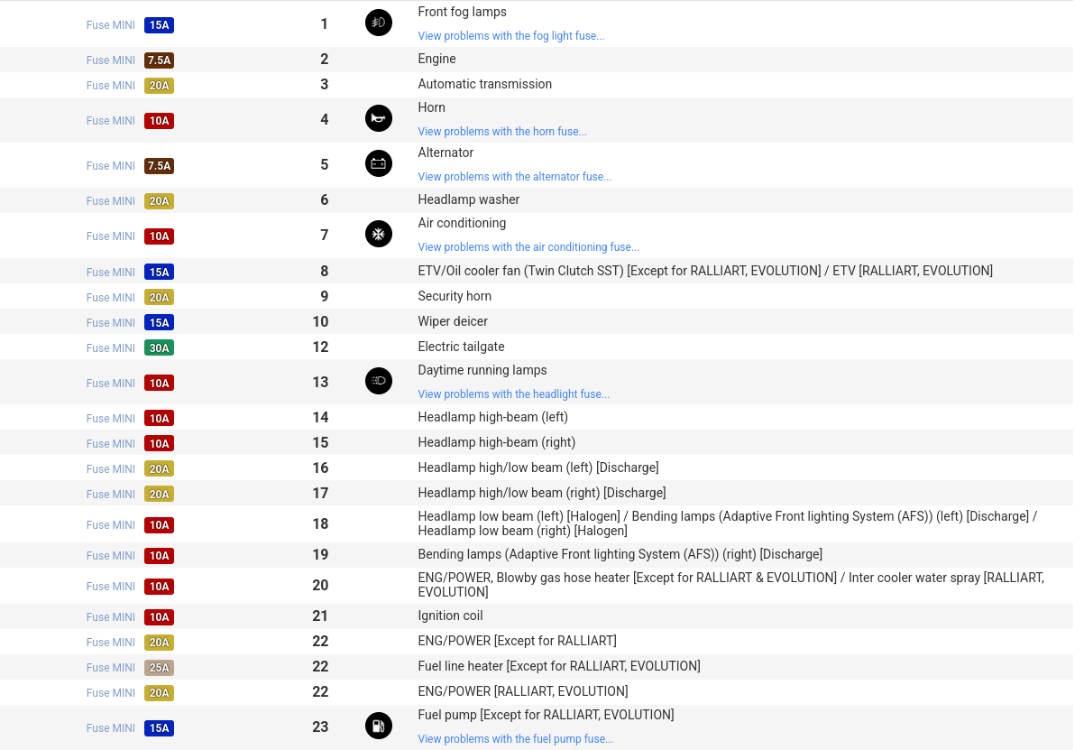
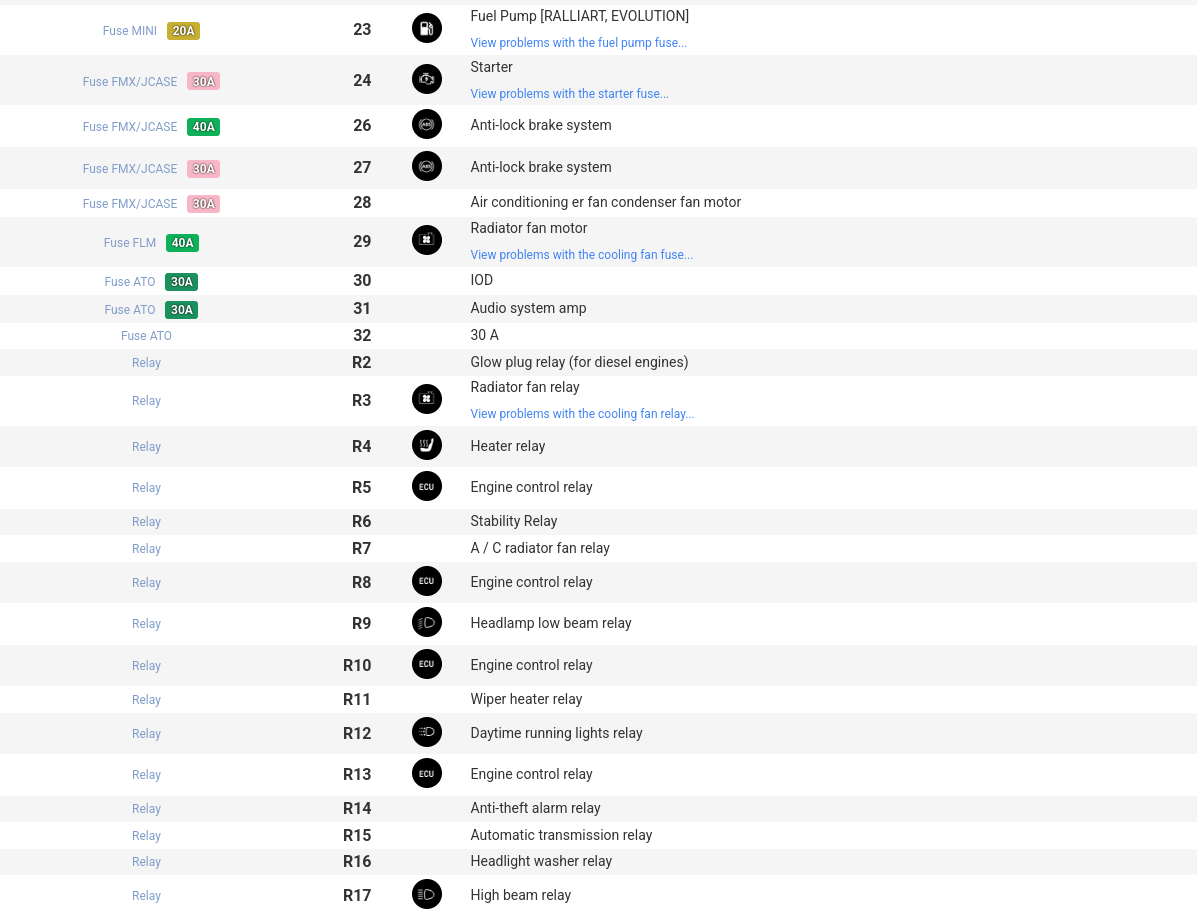
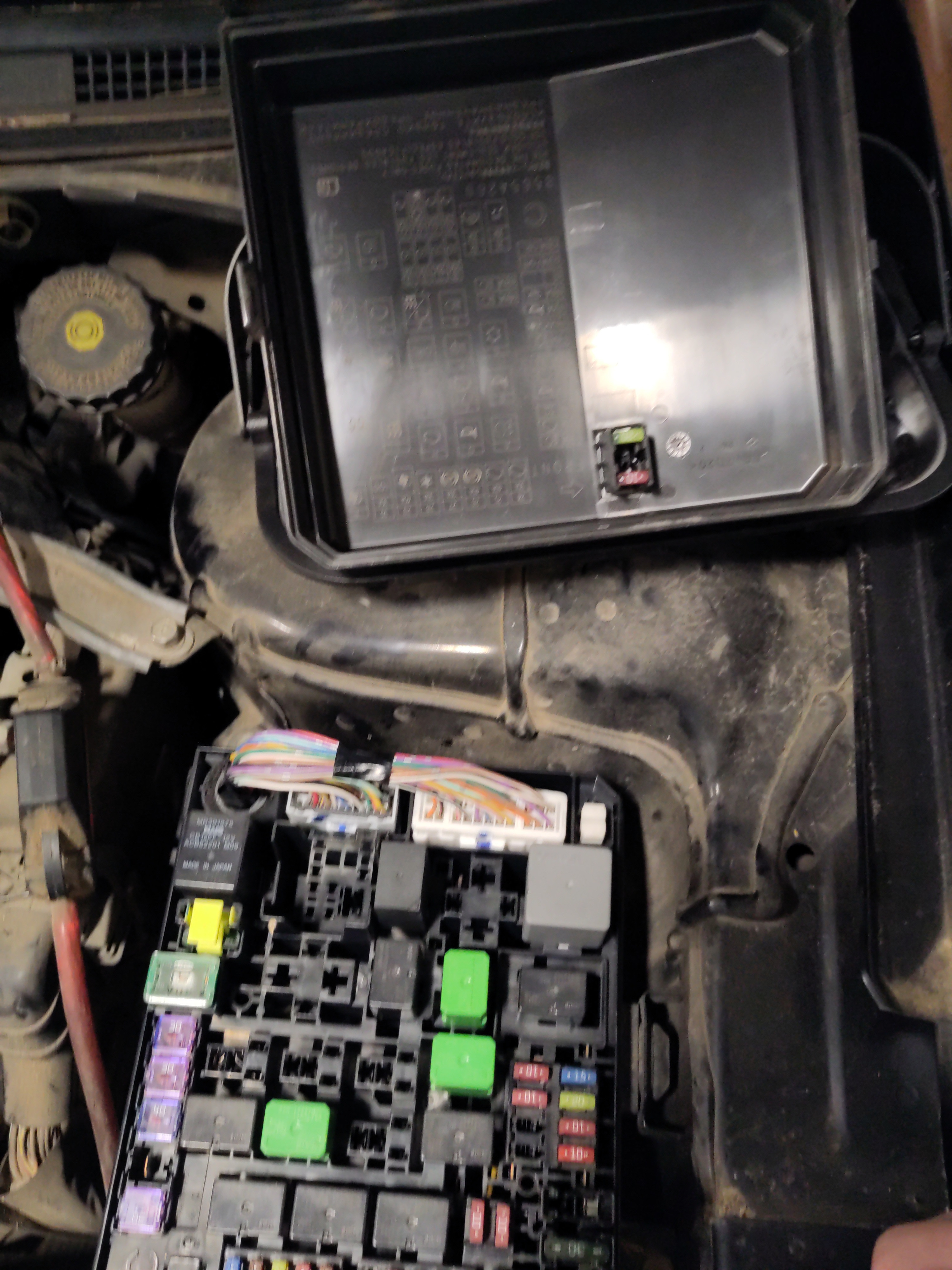
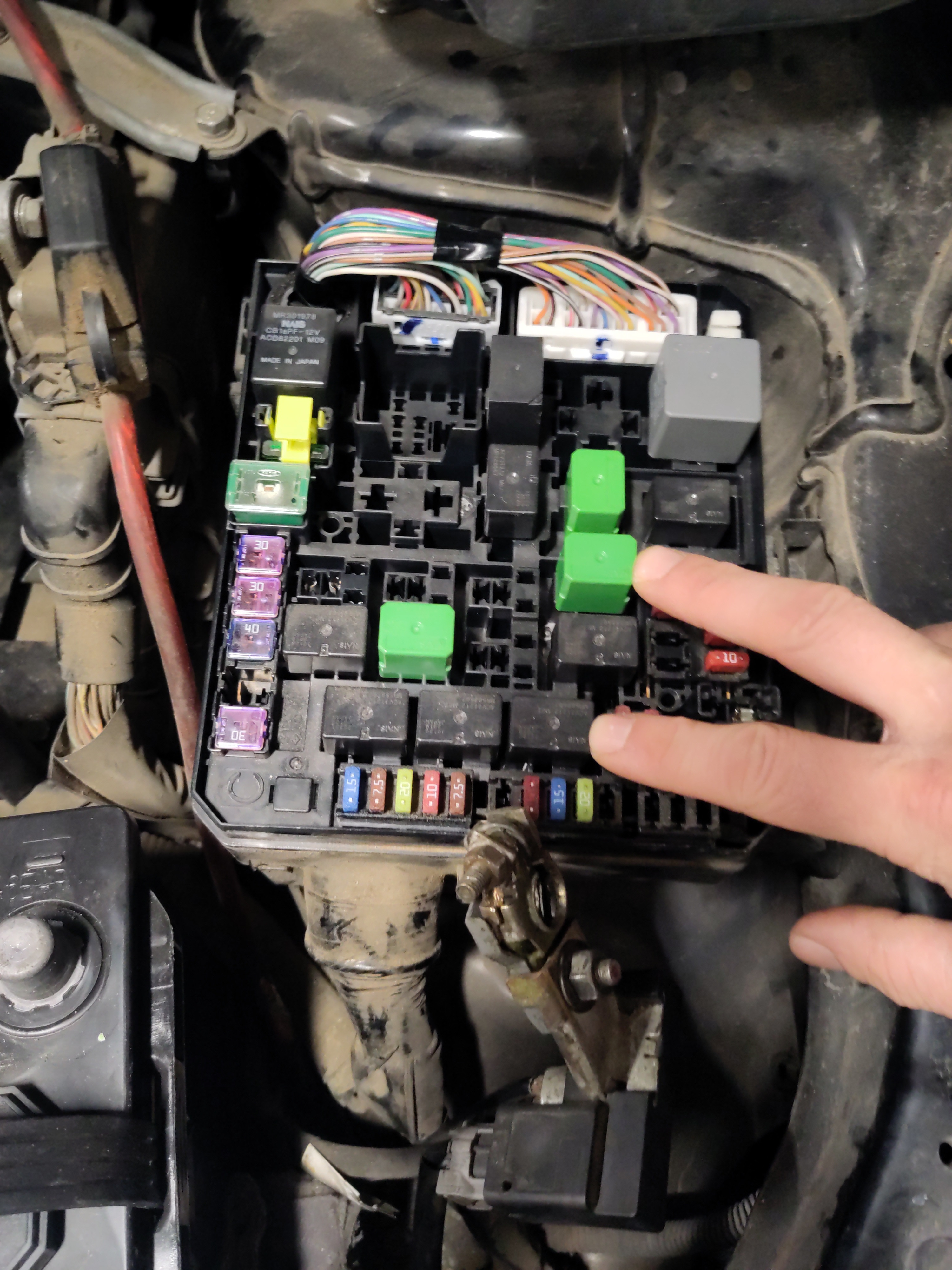
- Locate the anticipated malfunctioning relay. There is an engraved diagram in the lid of the to serve as a reference. The diagrams below show the fuse box in the engine (not in the cabin). Diagram below may be nuanced because of different sub-models or what subsystems installed. This URL: https://www.startmycar.com/mitsubishi/lancer/info/fusebox will be a great reference for other Mitsubishi Lancer years.
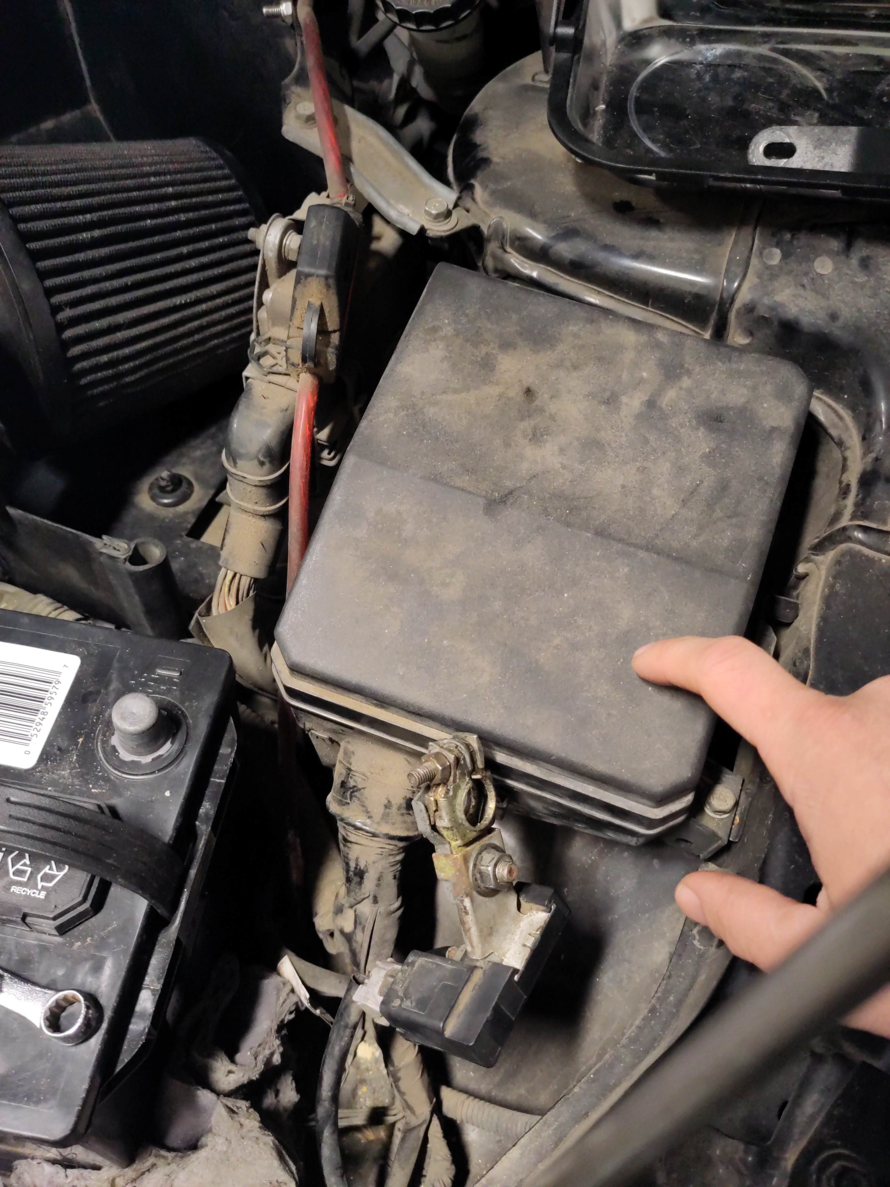
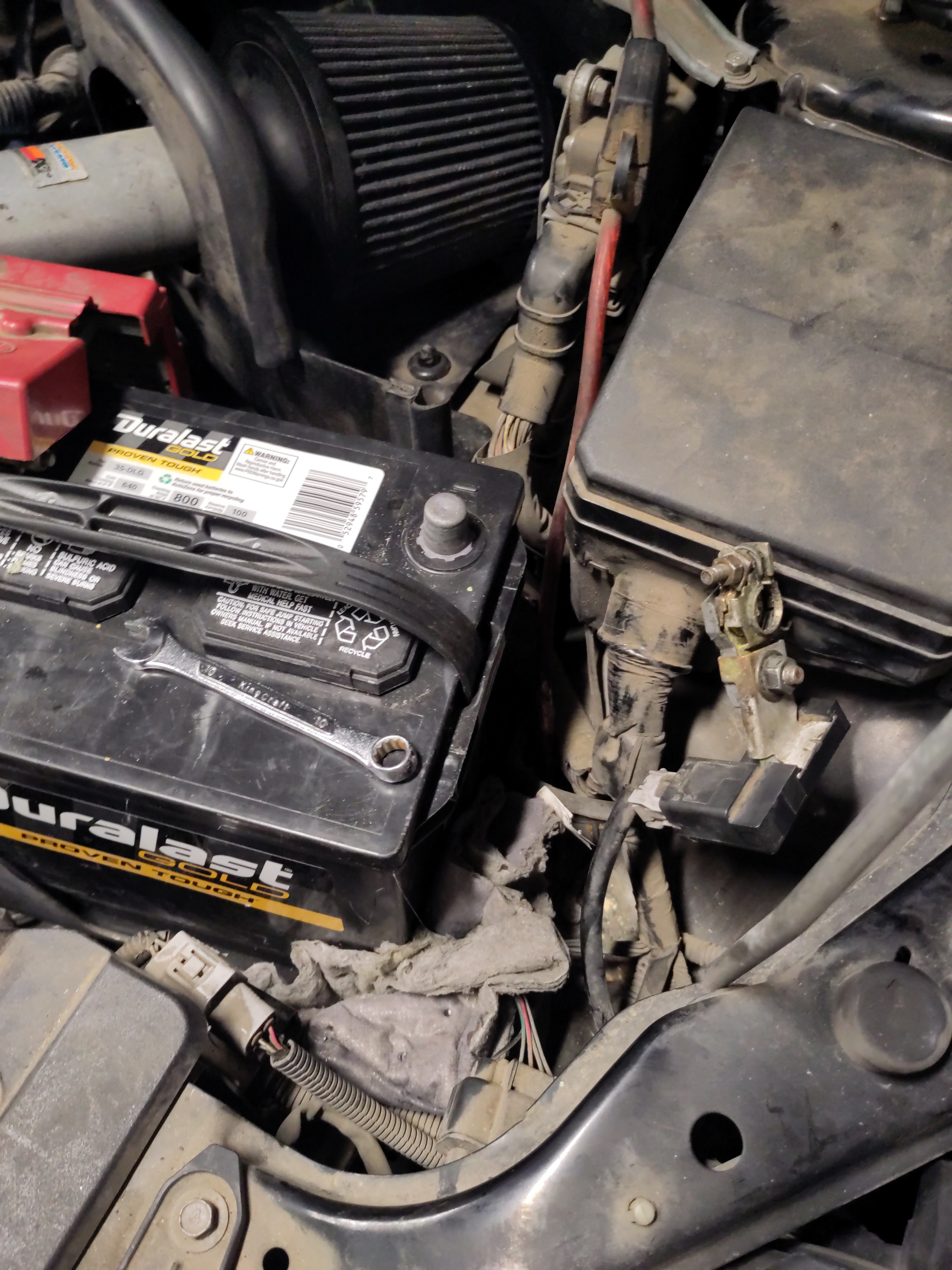
- Locate a black plastic box is to right from the air filter and sitting behind the battery.
- Remove the lid to gain exposure fuse box. Push back the clip to remove the lid and lift up on the lift itself.
- Disconnect from ground connection from the battery terminal using a 10mm wrench.
- Remove one of the relays by pulling up and wiggling it free.

Testing the Relays:
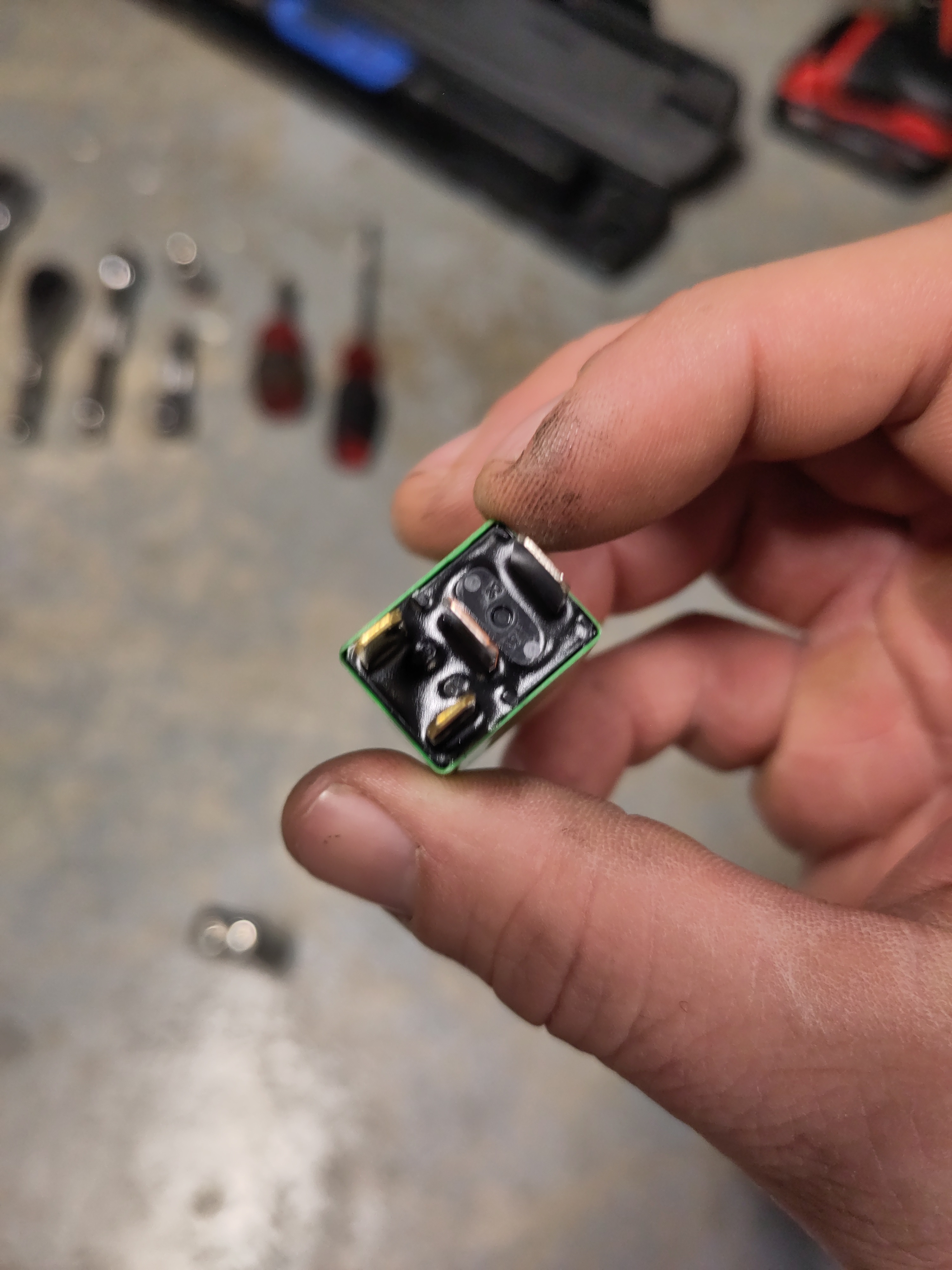
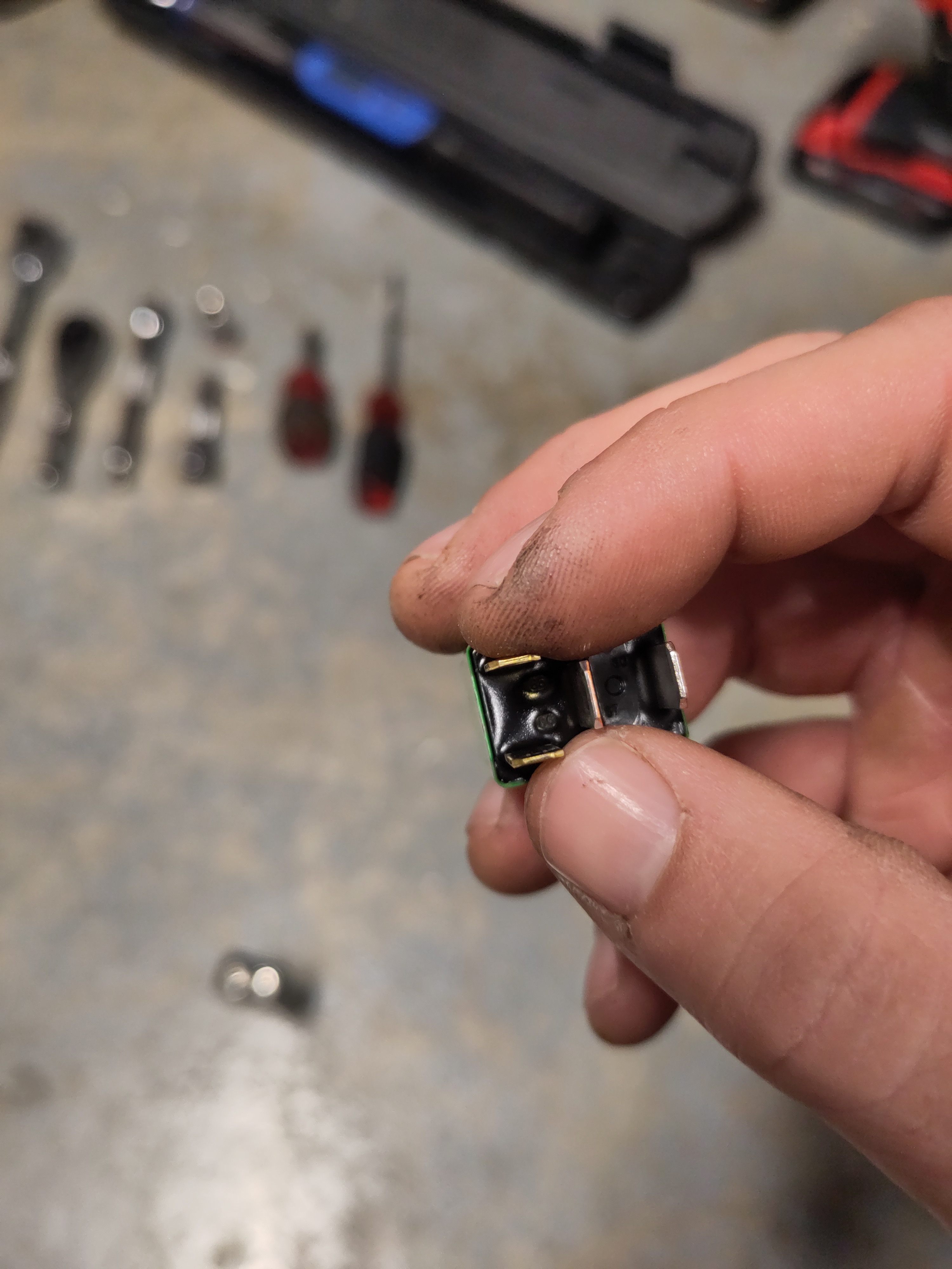
- There are four pins on the relays and they are numbered. Each numbered connection has a specific purpose. In this instance, testing the relay is the goal.
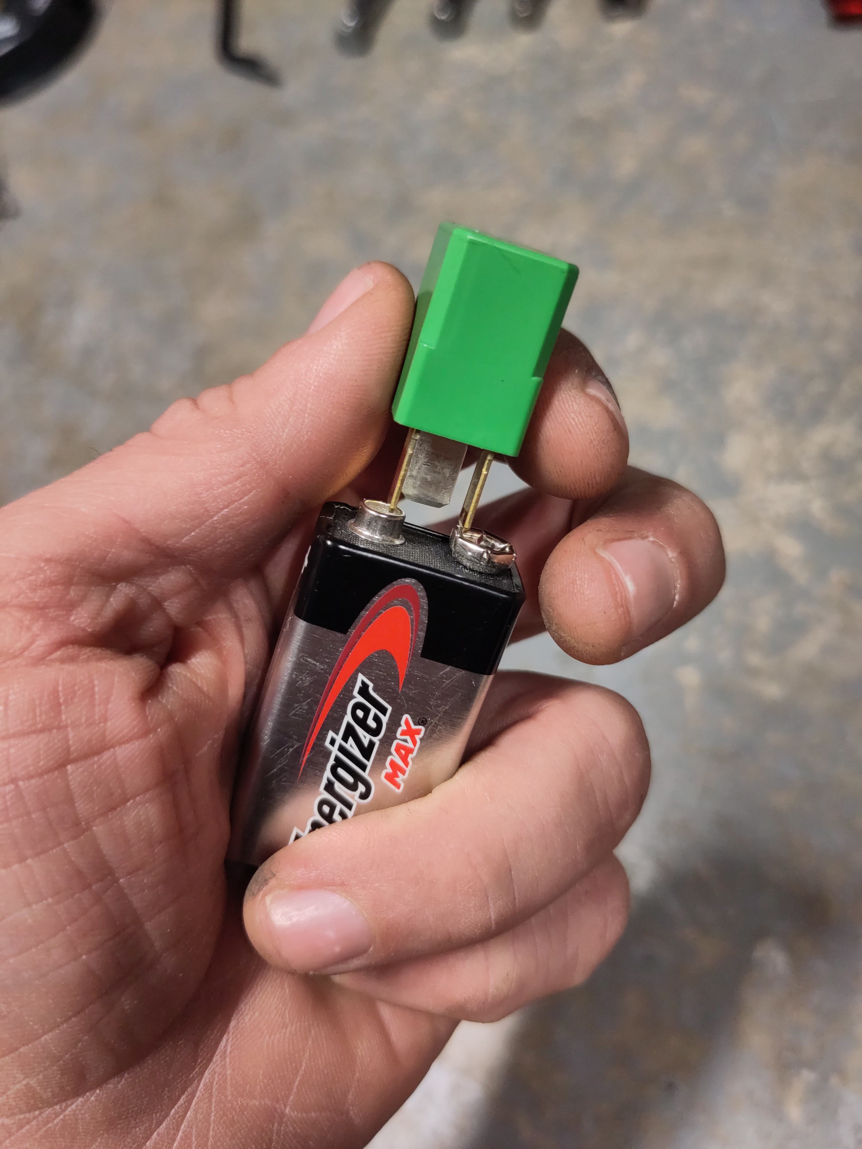
- Take a 9 Volt battery and connect the negative terminal to 85 numbered pin and positive terminal to the 86 numbered pin. There should be an audible click and should be able to feel the vibrations from the relay engaging. If there isn't audible click or felt movement, then the electromagnetic relay is faulted.
Other Tests:
Use a multi-meter to measure the resistance of number 85 pin and 86 numbered pin. The resistance would be in a range of 100 Ohms to 150 Ohms. Swamping the suspected malfunctioning relay with another relay to see if the problem persists.
References:
- https://www.startmycar.com/mitsubishi/lancer/info/fusebox
- https://www.shenler.com/new/5-common-causes-of-electromechanical-relay-failure-and-how-to-fix-them/
- Multimeter test: https://www.youtube.com/watch?v=mkjSFnHSSis
- 9V test:https://www.youtube.com/shorts/ijNtEcg6_g4
- Fuse Box Diagram: https://www.startmycar.com/mitsubishi/lancer/info/fusebox
- https://car-box.info/mitsubishi/lancer/10-cy-2007-2017.html