Functionality & Purpose:
The starter is a key component of a vehicle's ignition system. It is responsible for producing the cranking action that occurs when the ignition key is turned. If the engine does not crank, a faulty starter may be one of the possible causes. The starter is a DC electric motor that converts electrical energy from the battery into mechanical energy, which is used to turn the engine over and initiate the combustion process.
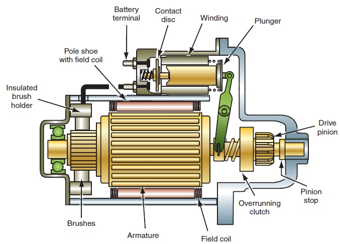
The operation of the starter begins when the 12-volt supply from the battery is delivered to the starter solenoid. The solenoid converts the electrical energy into mechanical motion, engaging the starter drive gear with the engine's flywheel. At the same time, electrical current is supplied to the starter motor, causing the armature shaft to rotate. As the armature rotates, the starter gear also turns, cranking the engine and initiating the starting process.
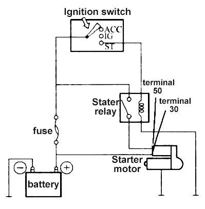
This diagram illustrates how the starter operates within the vehicle's ignition system. When the ignition key is turned, a signal is sent to the starter relay and the Engine Control Module (ECM). The ECM then verifies the necessary conditions for starting and allows the battery to supply voltage to the starter solenoid. Once energized, the solenoid engages the starter motor, which cranks the engine. The signal wire is essential because it activates the starter circuit; without this signal, the starter will not engage or operate.
Removal:
This repair involves several detailed steps and a significant amount of information related to the starter system. However, some procedures have been omitted from this tutorial for the sake of simplicity and to keep the guide concise. Examples include raising the vehicle and securing it on jack stands, as well as removing the plastic underbody shields. Depending on the condition of the vehicle, this repair may take a considerable amount of time and unexpected complications may arise. Patience and careful attention to detail will help ensure a successful outcome. Additionally, this particular Mitsubishi Lancer has several modifications that make the starter replacement procedure slightly different from the standard process. As a result, some of the steps in this tutorial may vary from those found in factory service manuals or other guides. At the time this repair was performed, the vehicle was inoperable and certain components, including the plastic underbody shield, had already been removed, which affected the sequence of the procedure.
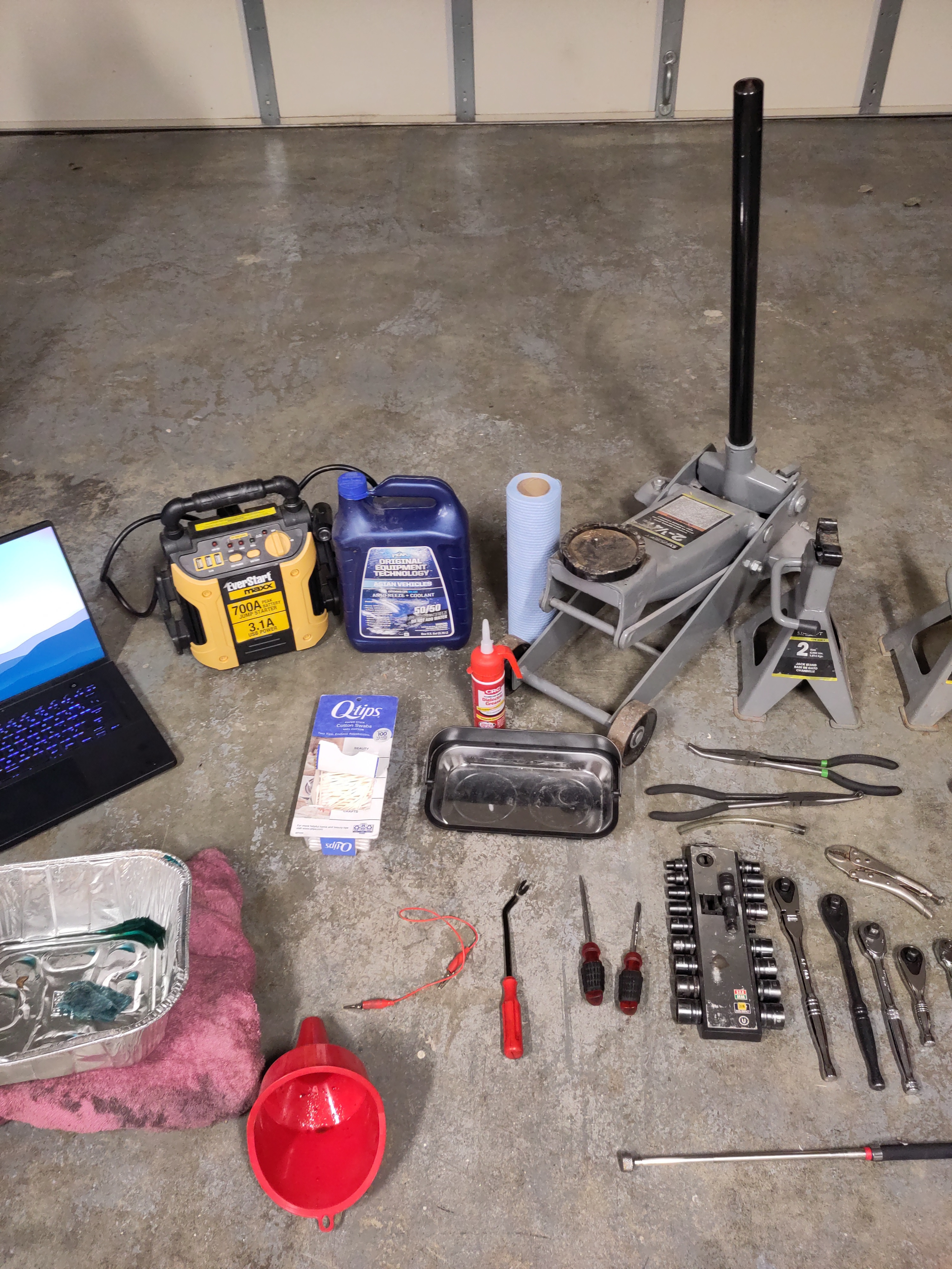
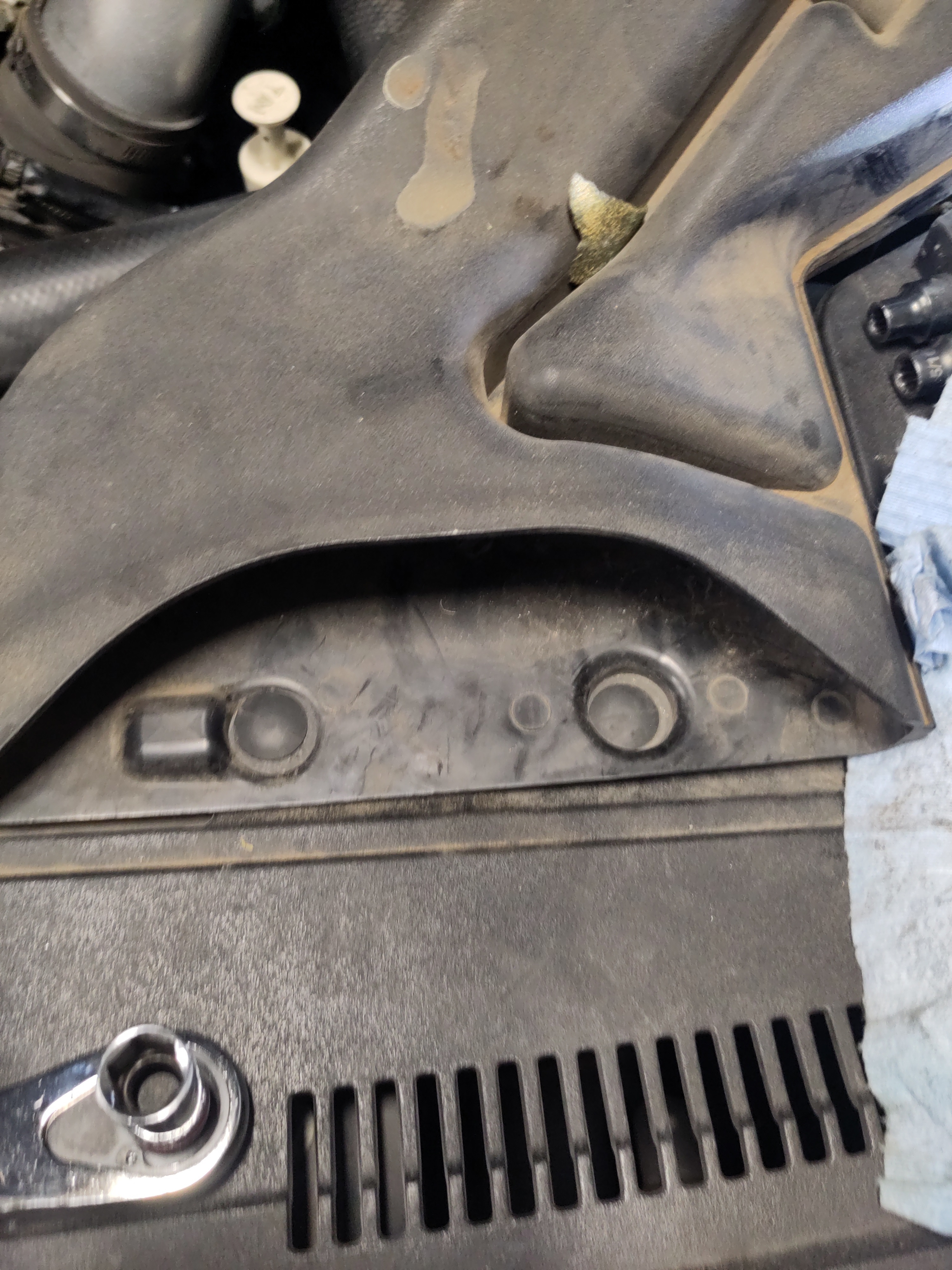
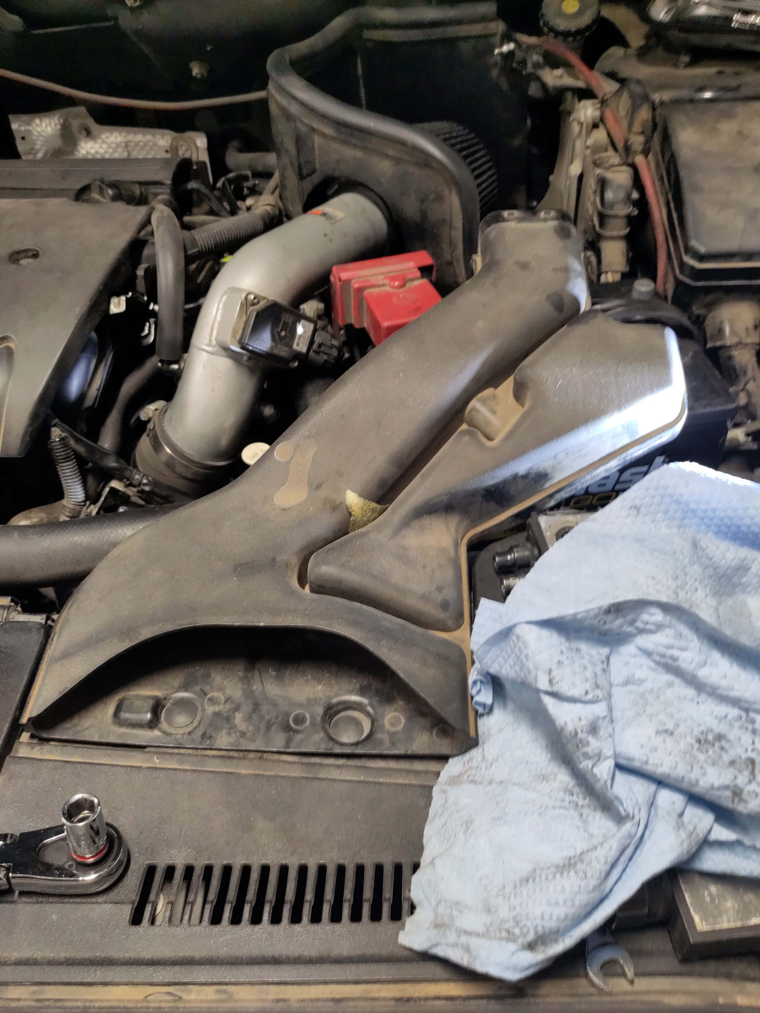
- Remove the plastic air intake by pulling up on the clips with either a flat screw driver or push pin fastener removal tool. Store them in the magnetic pan for safe keeping.
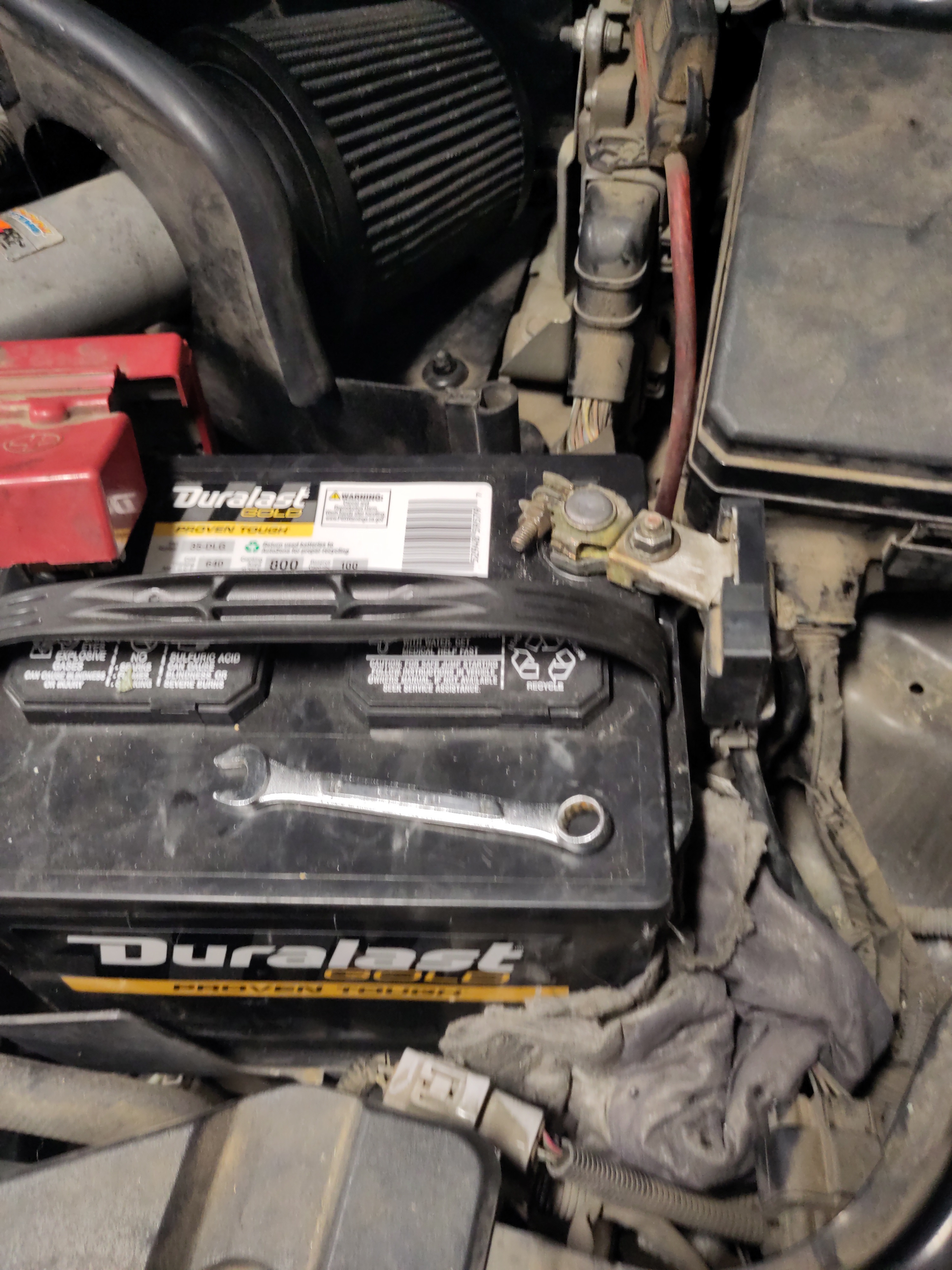
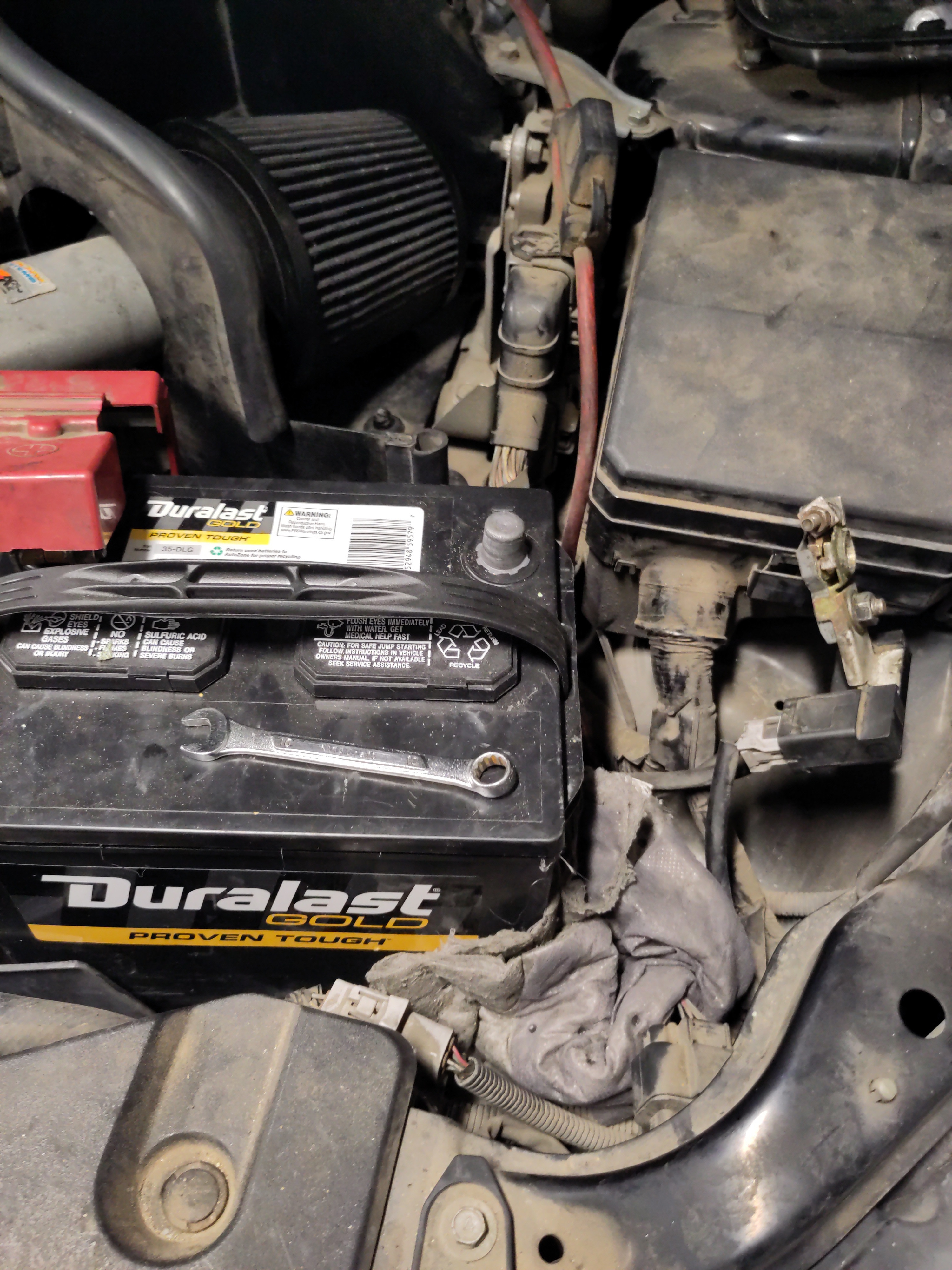
- Disconnect the ground electrical connection from the battery terminal using the 10mm wrench.
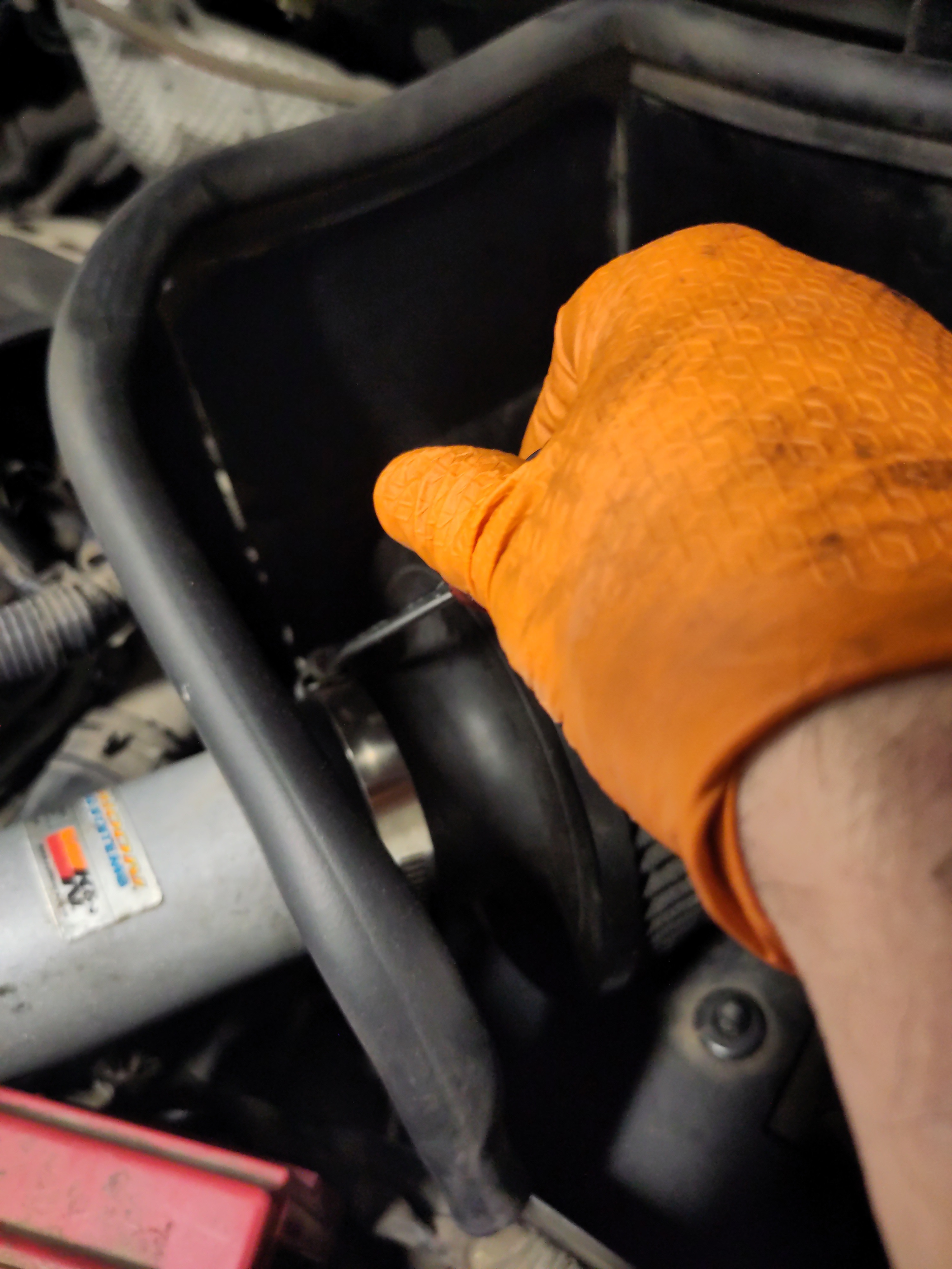
- Using a flat screwdriver loosen the hose clamp, and then wiggle and pulling off the the air intake filter from the pipe.
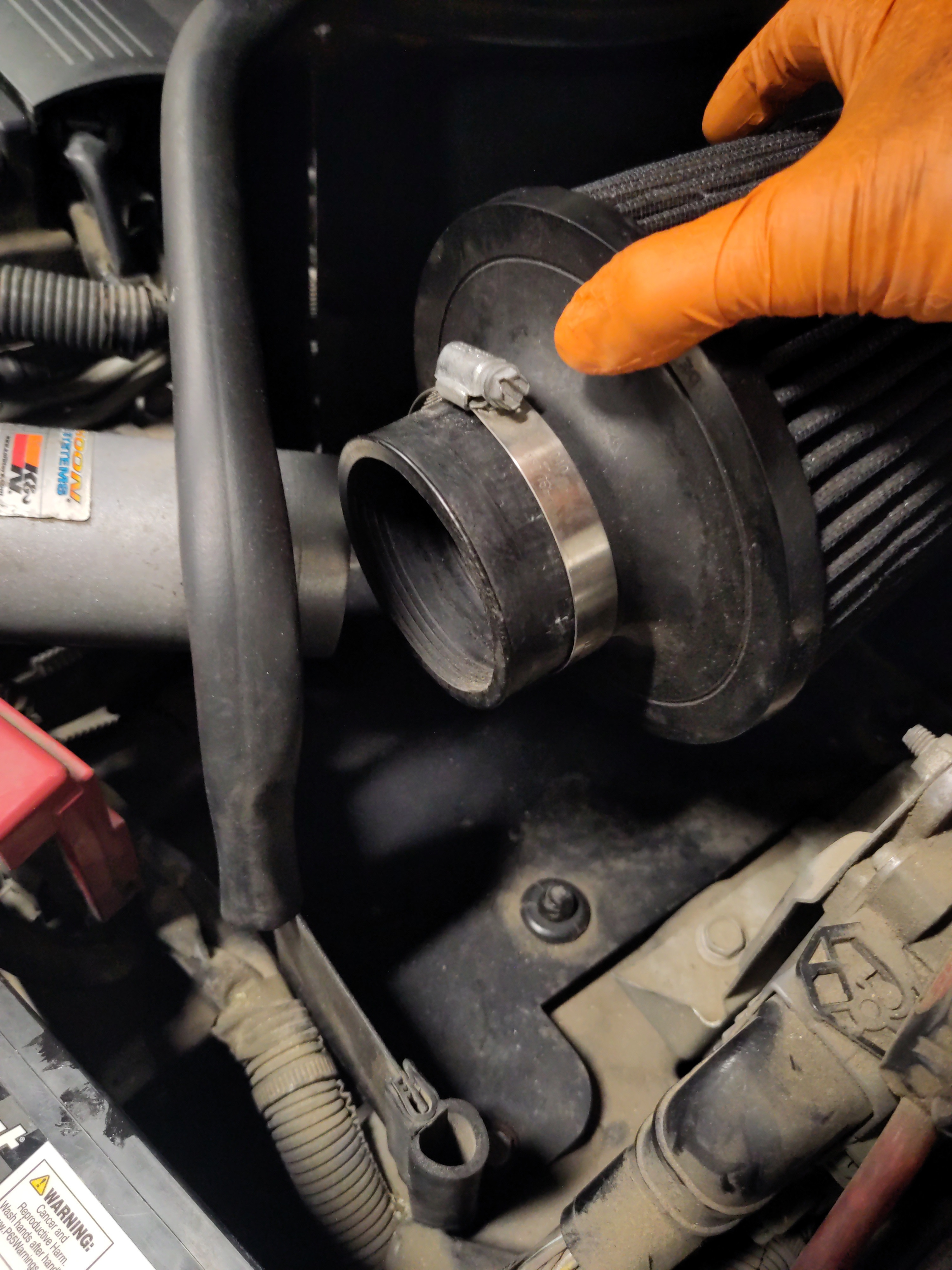
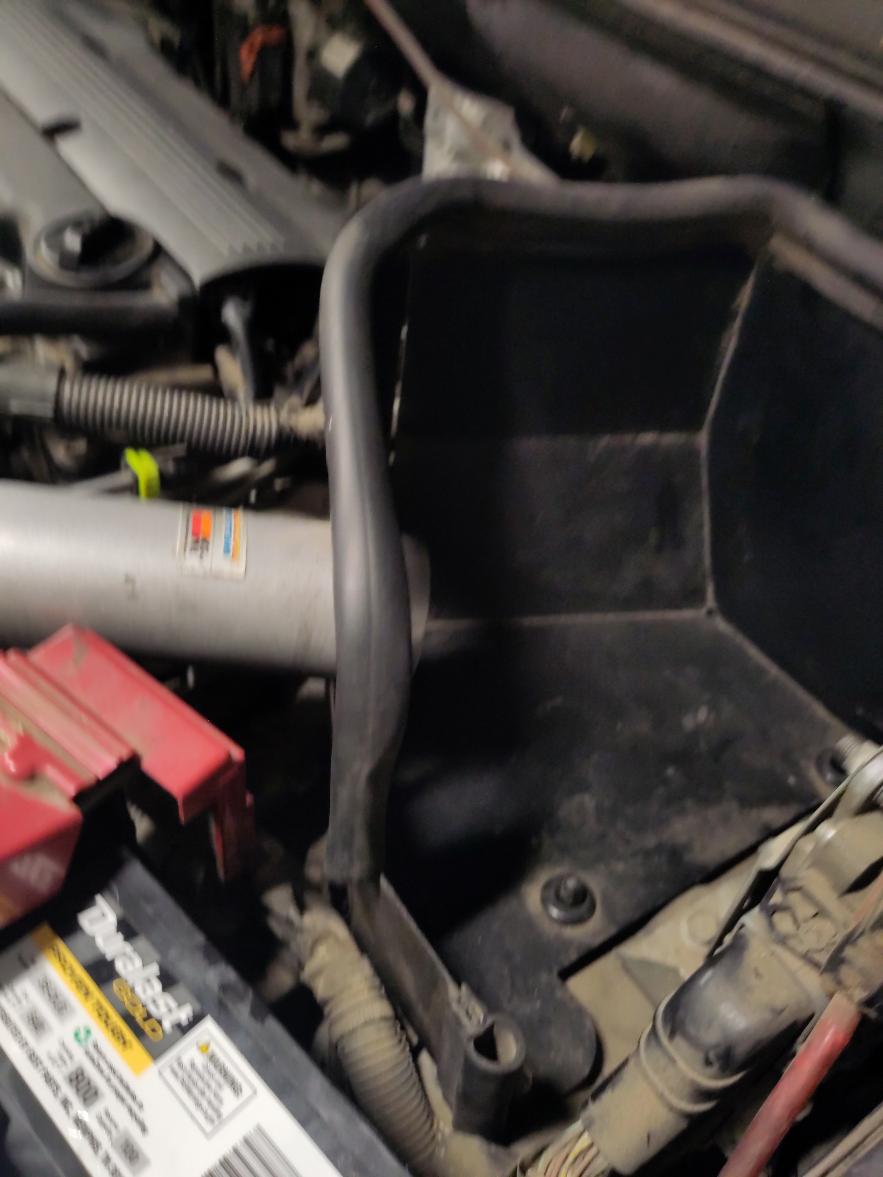
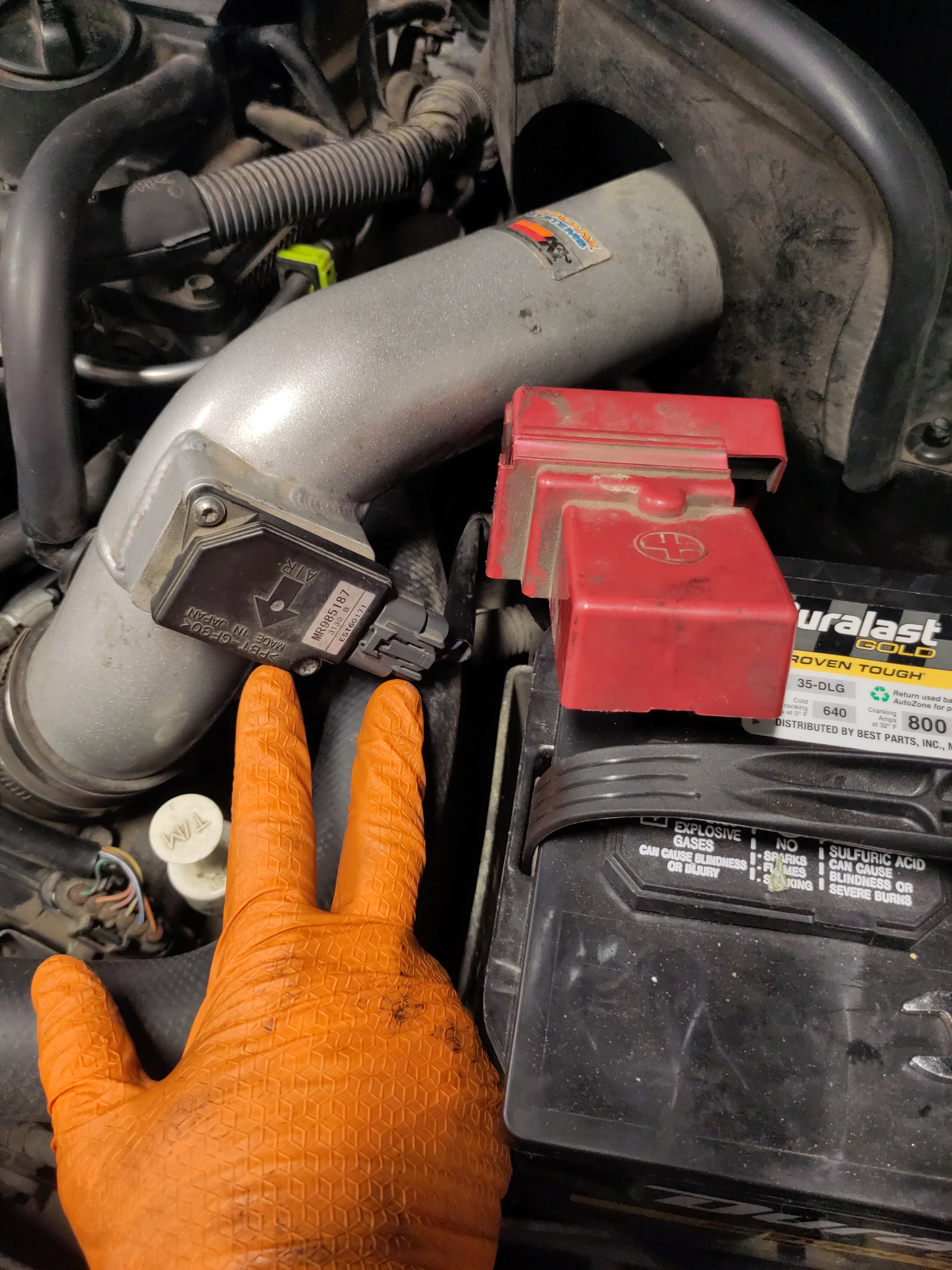
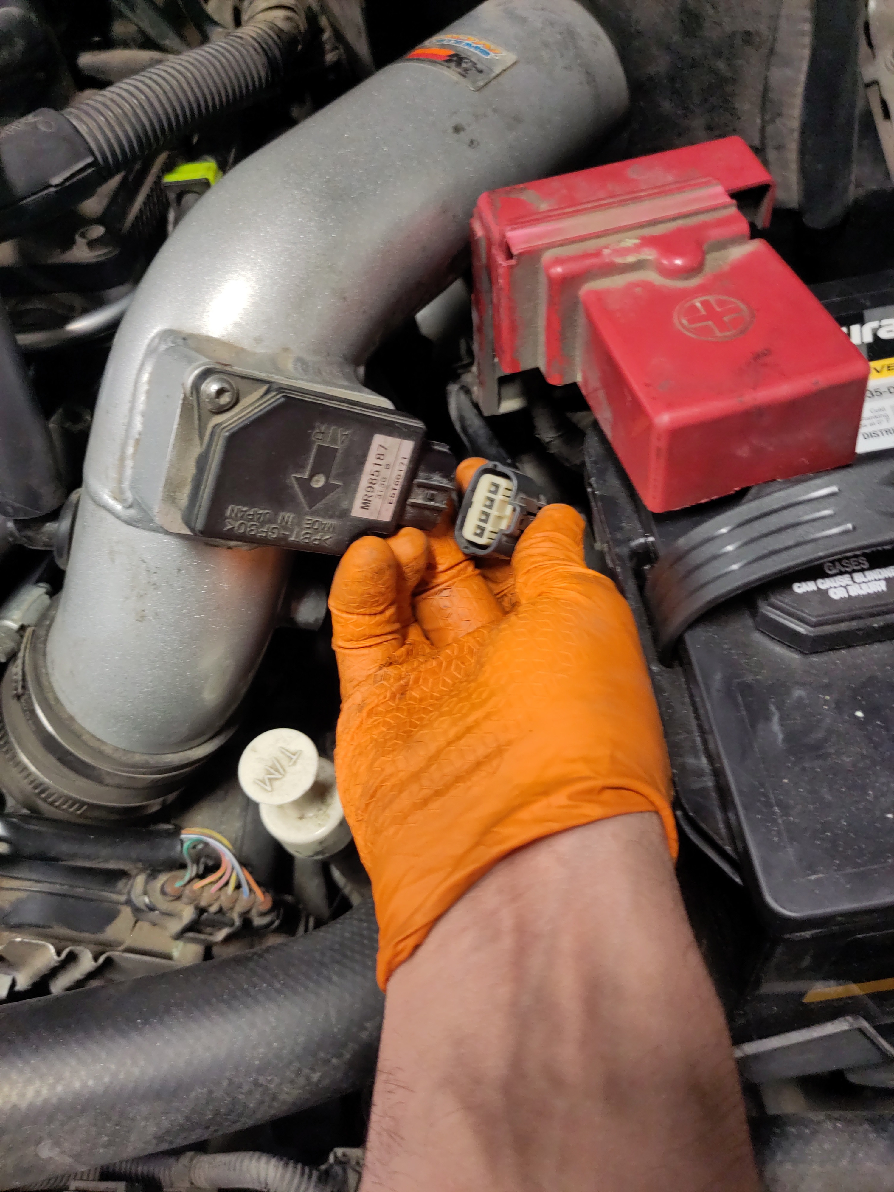
- Next remove the electrical connection from the Mass Air-Flow Sensor by pushing in the clip and pulling the connection away from the Mass Air-Flow Sensor.
- The hose clamp securing the air intake pipe to the throttle body needs to be unscrewed. Using a flat head screwdriver, unscrew the top hose clamp and loosen it just enough to remove the air intake pipe by pulling it up and wiggling it if necessary.
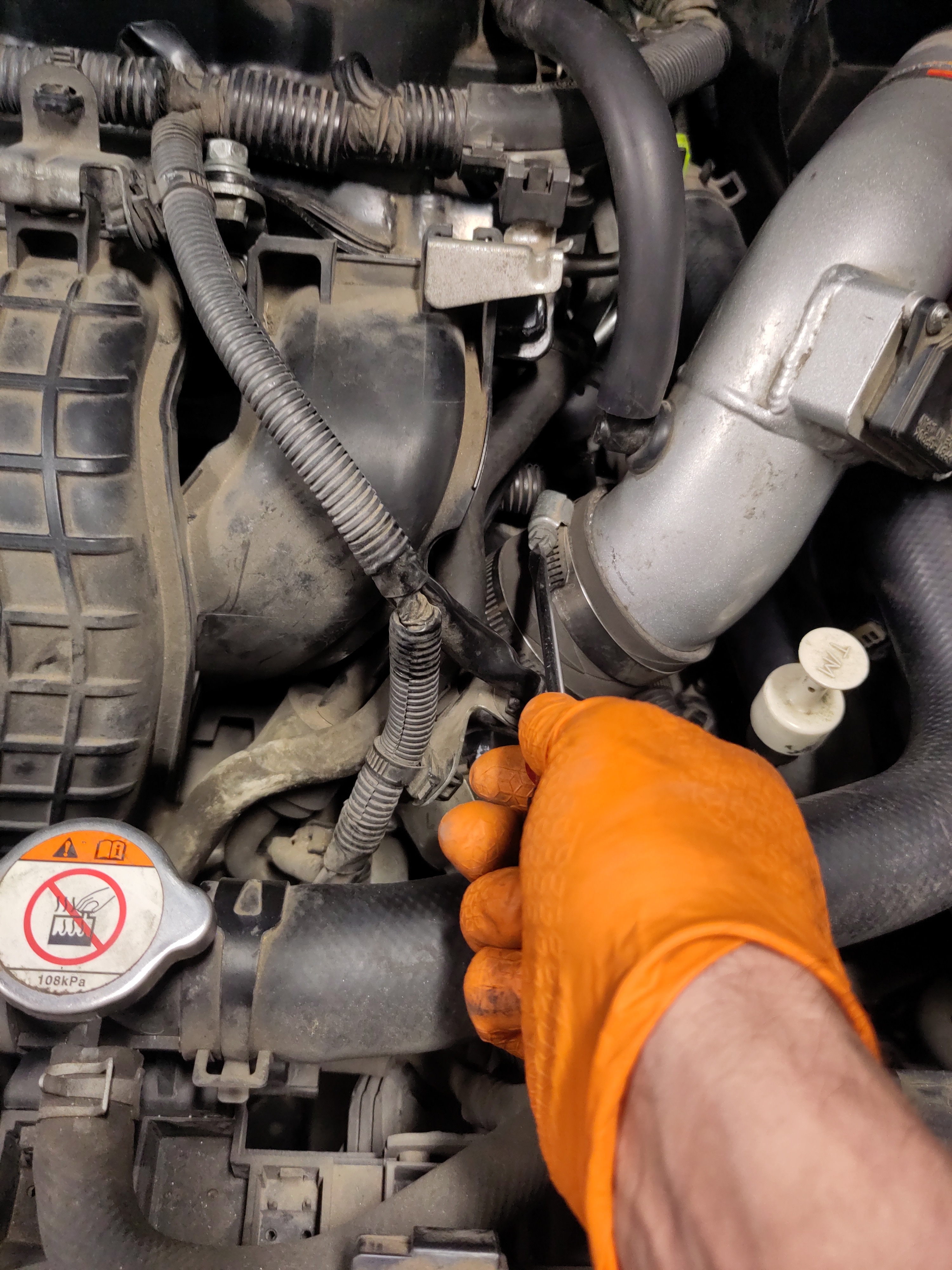
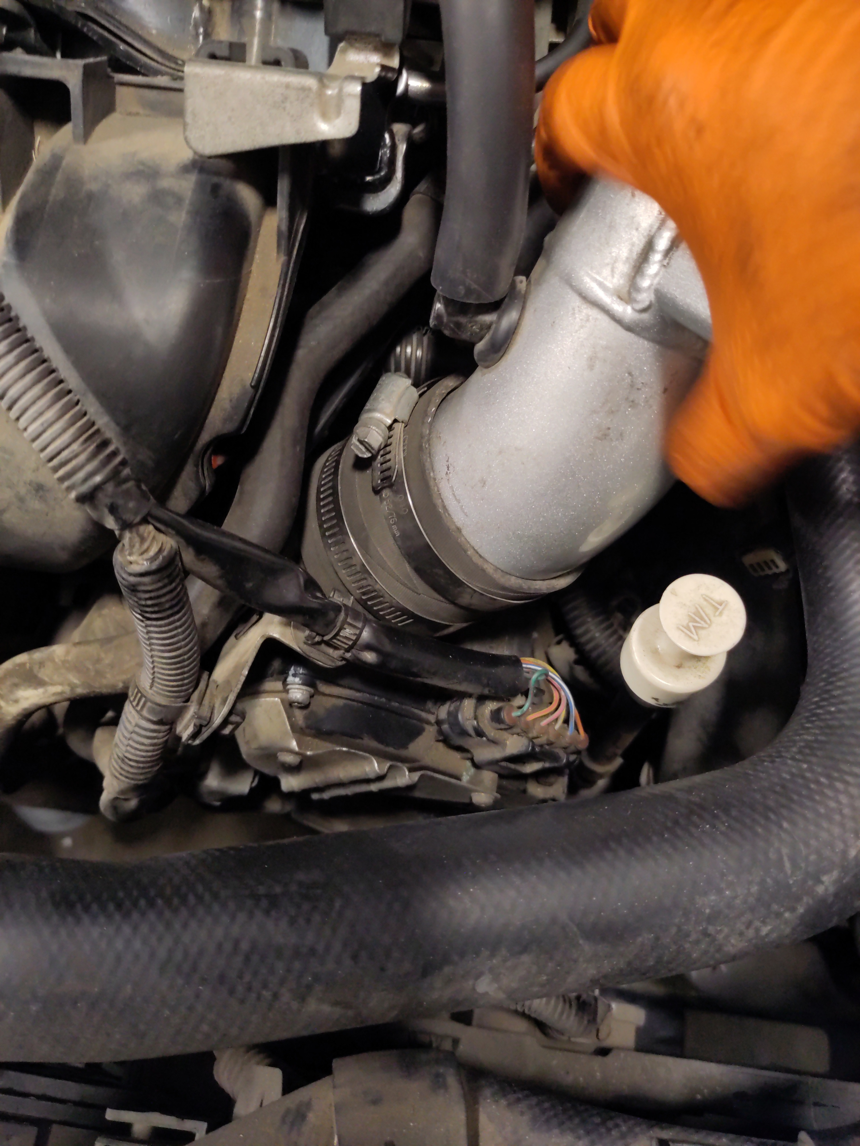
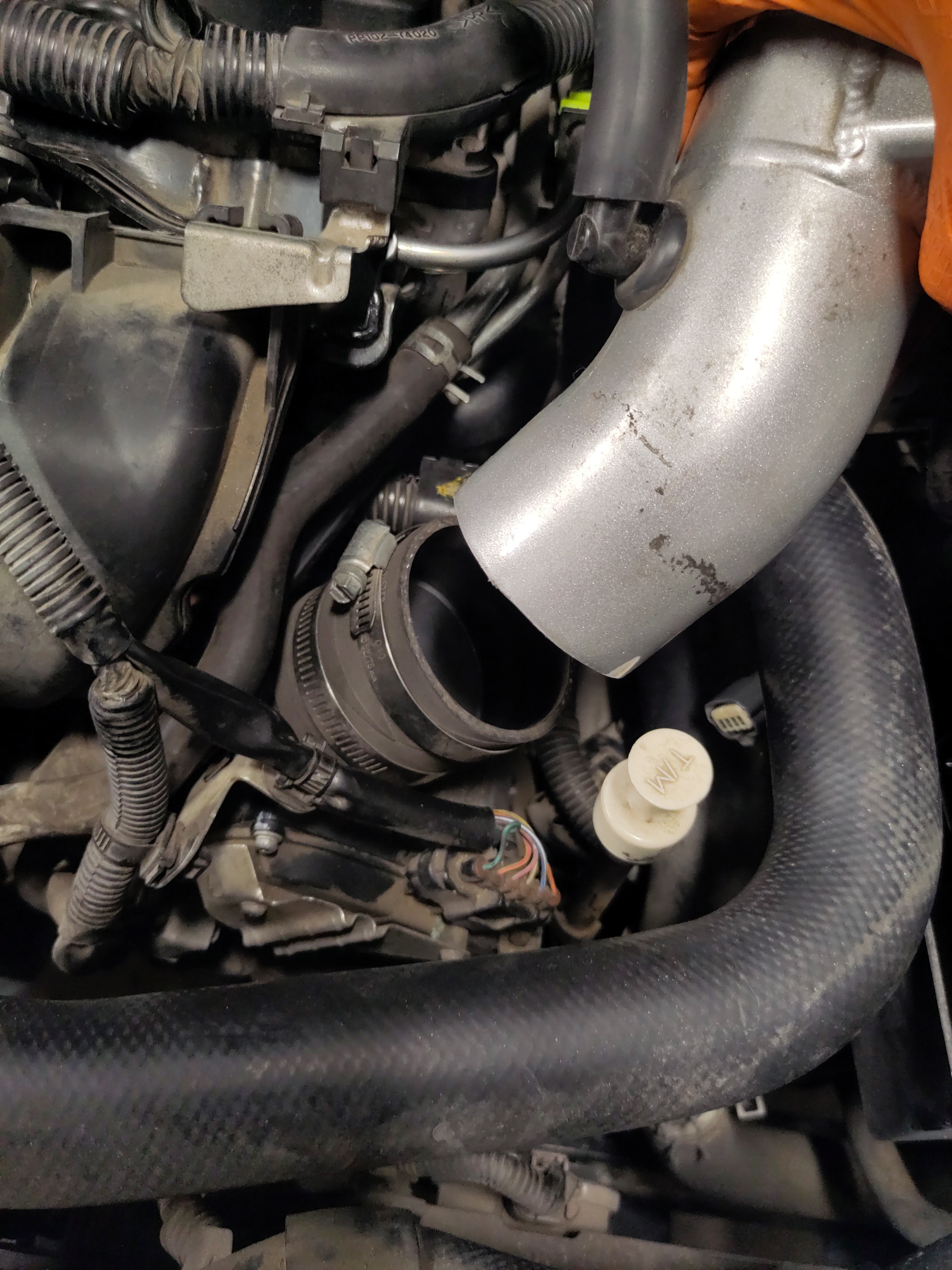
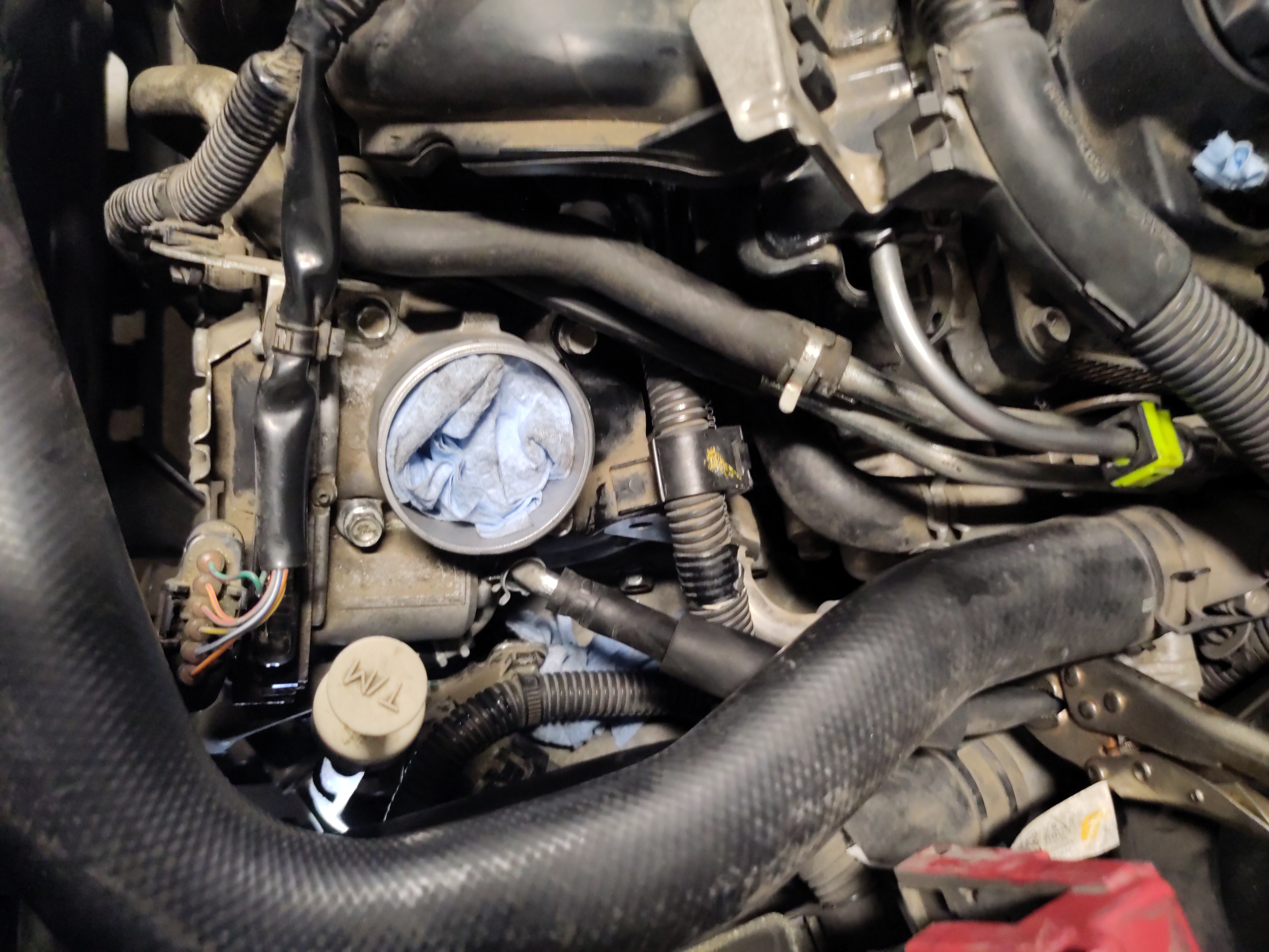
- IMPORTANT! Take a piece of paper towel and stick it into the throttle body entry point. This is to prevent any debris entering the engine.
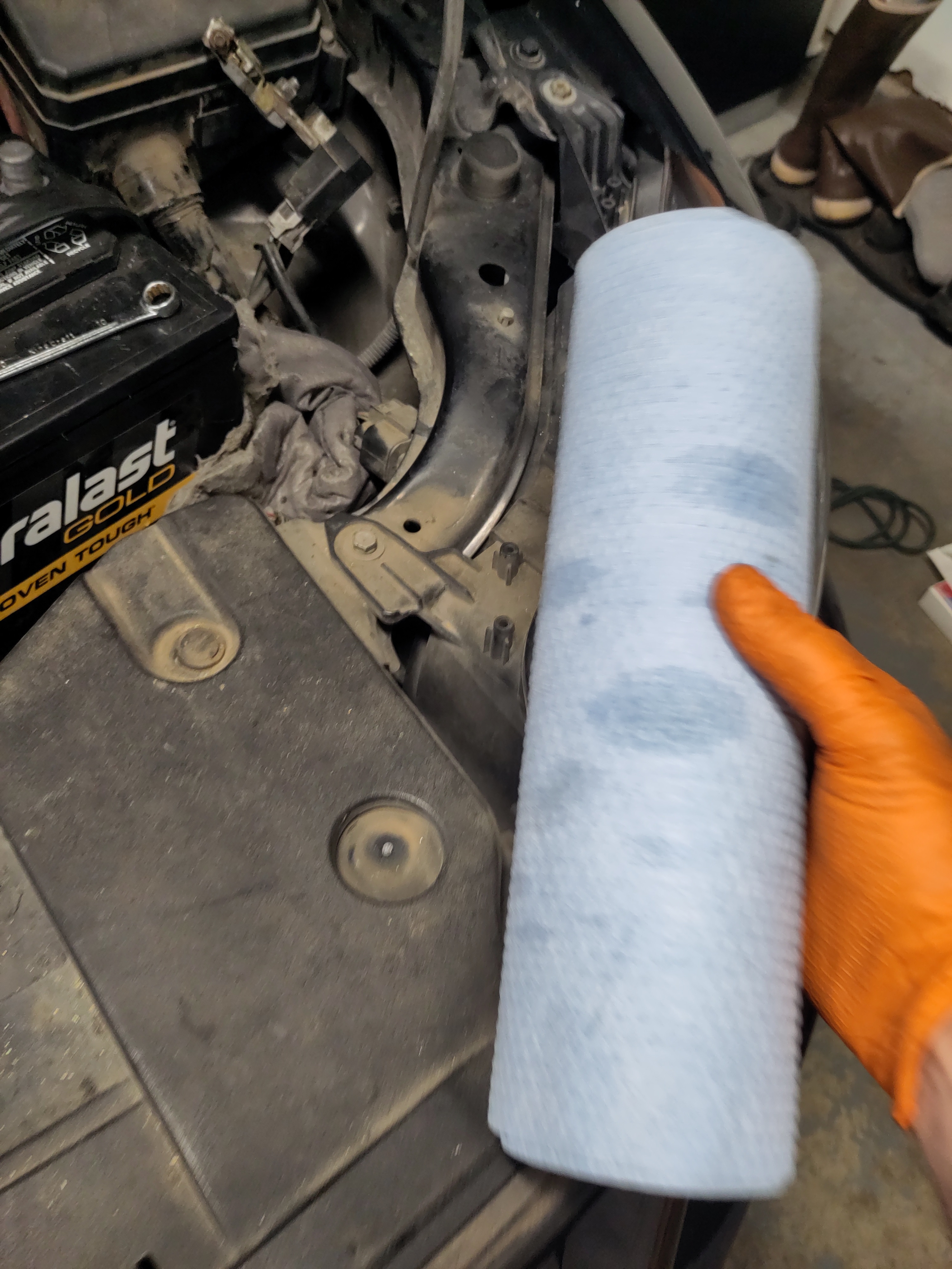
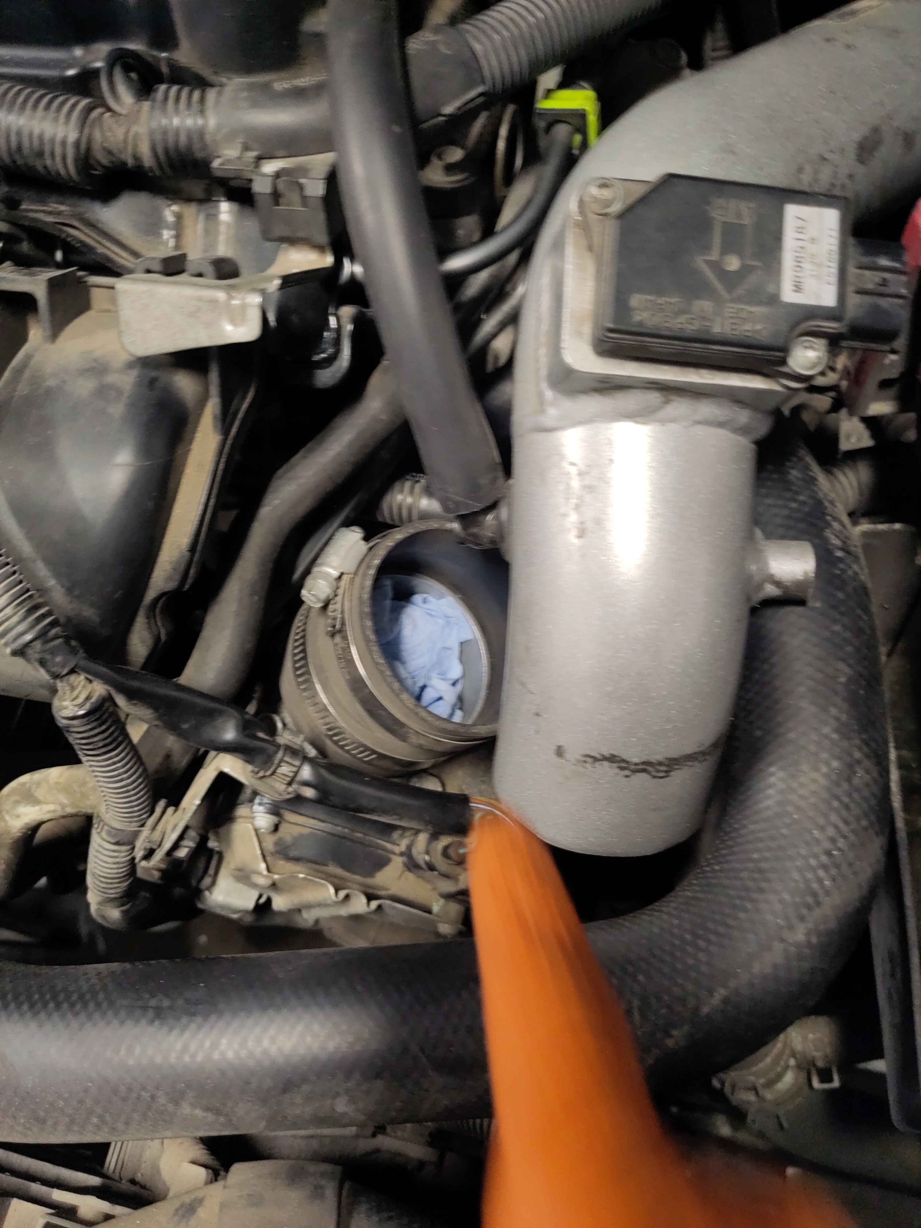
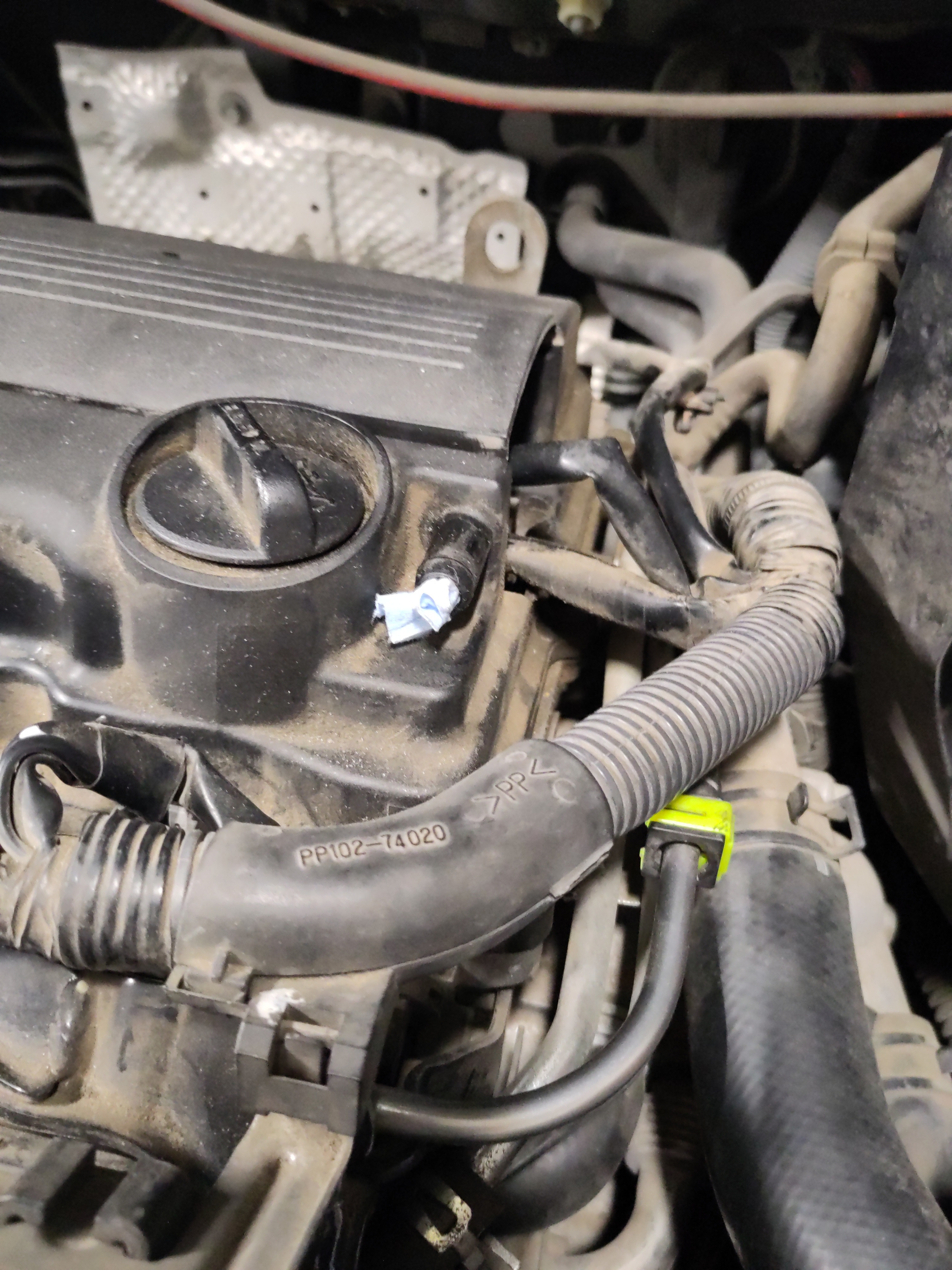
- Next remove the suction hose (small black hose) connecting from engine to the intake pipe. Remove the hose by pulling on it. Rip a small piece of paper towel off and stick the piece into the entry point. This prevention from debris entering the vehicle. Now the air intake pipe off to the side.
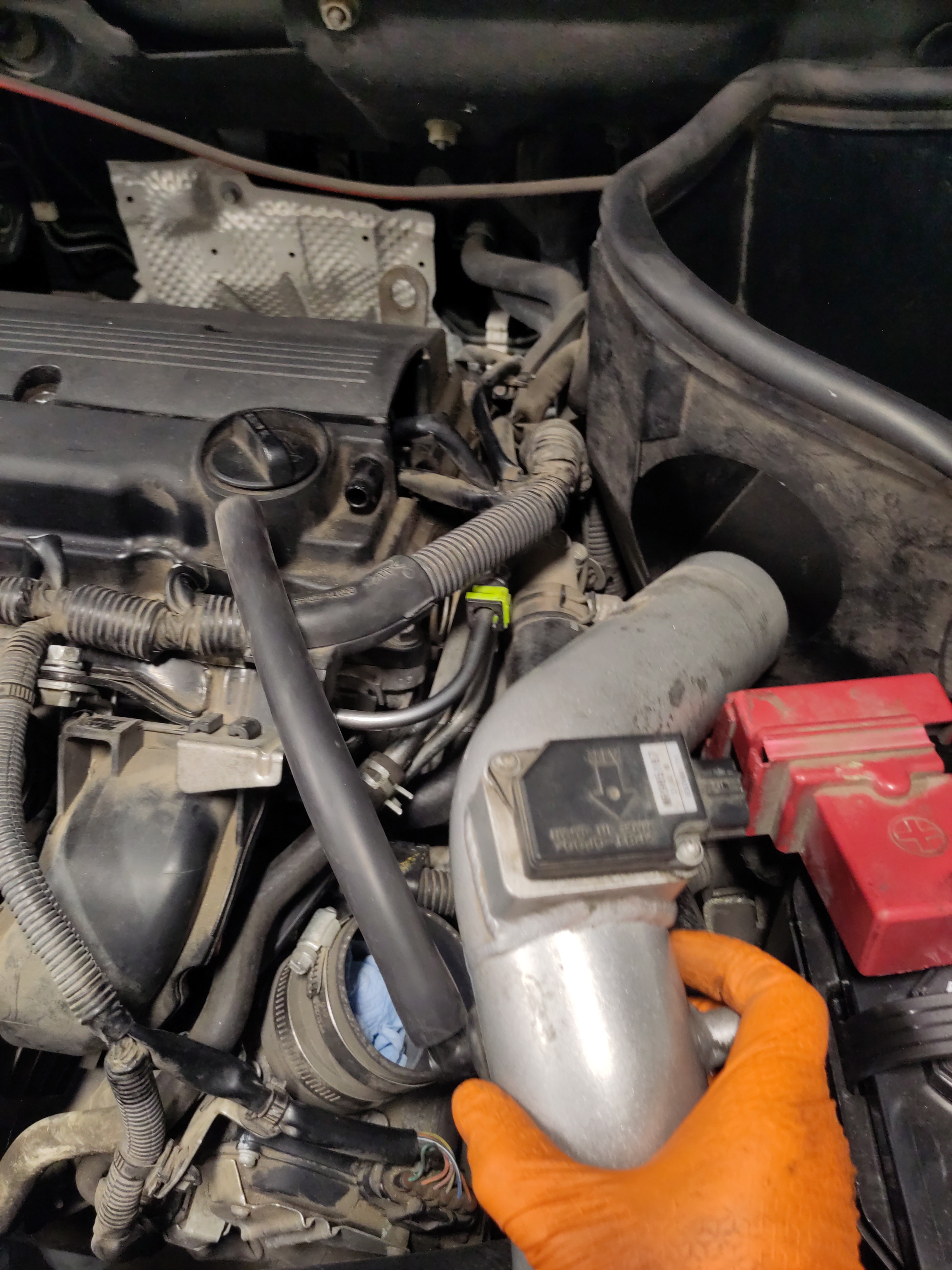
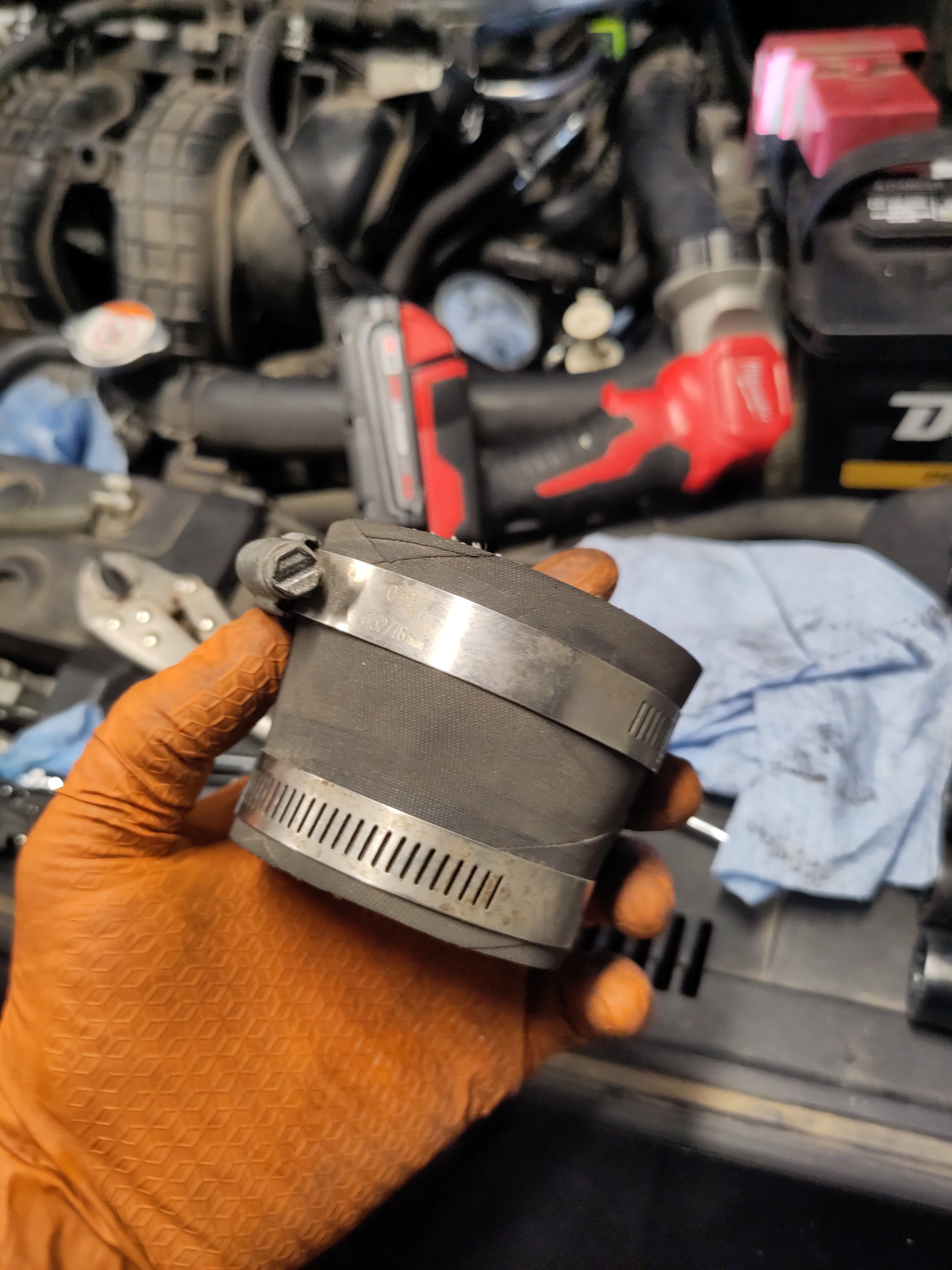
- The removal the hose connecting the throttle body and the air intake pipe will be removed by unscrewing the bottom hose clamp. Unscrew the hose clamp just enough to where the hose clamp to tight around the hose clamp, but loose enough to remove the hose. Set aside the hose.
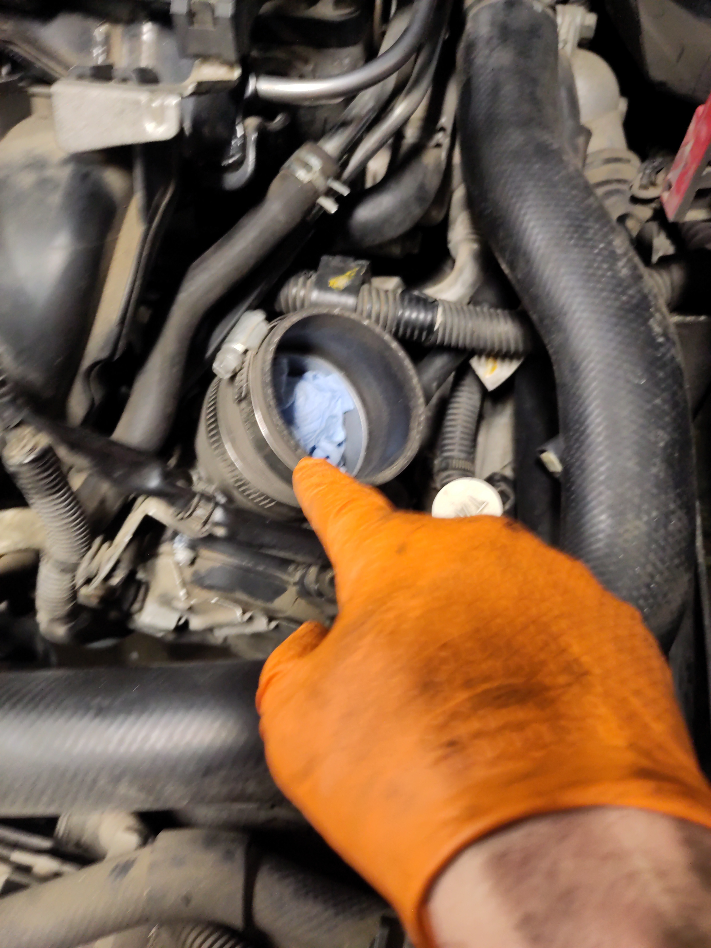
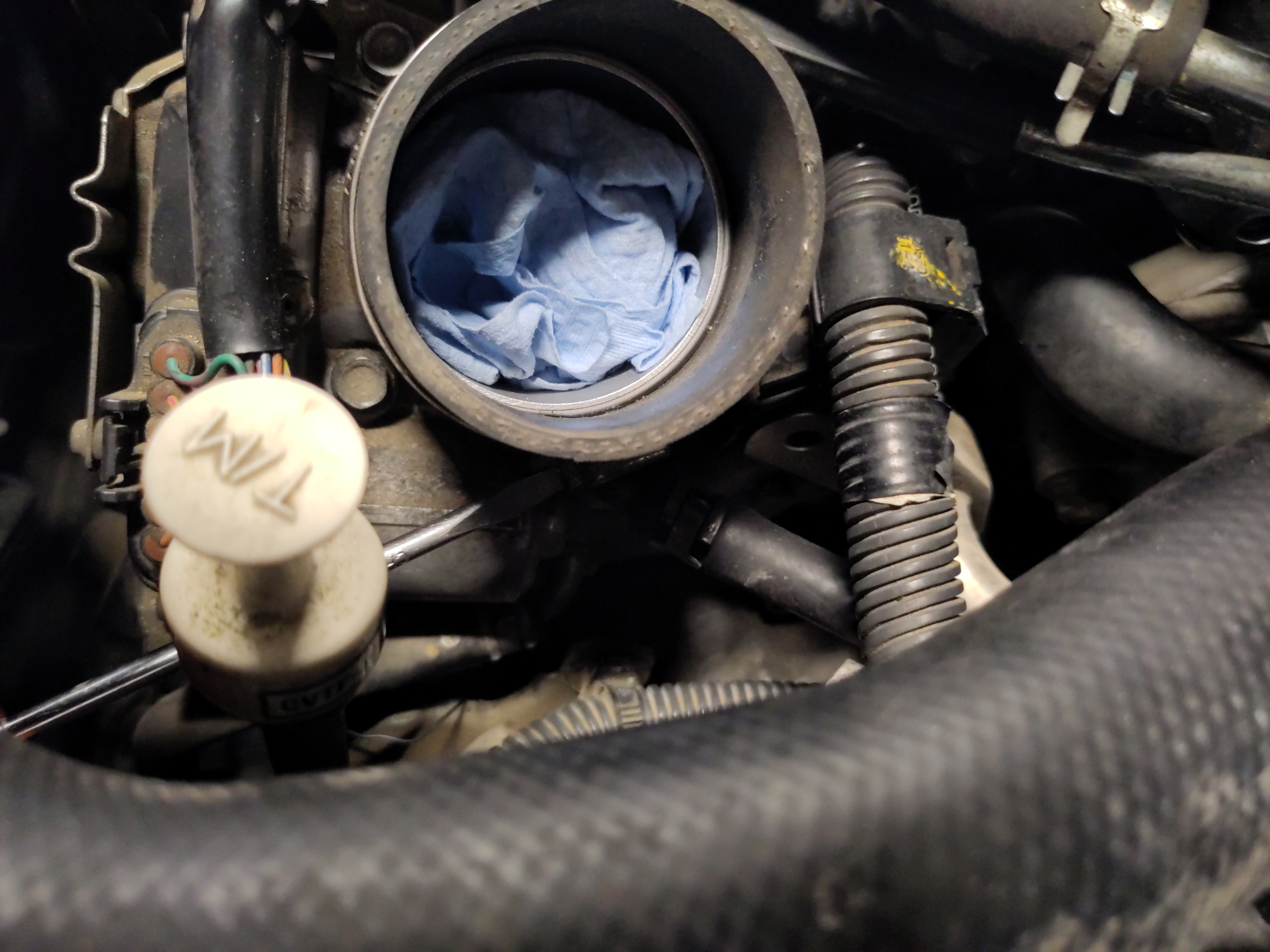
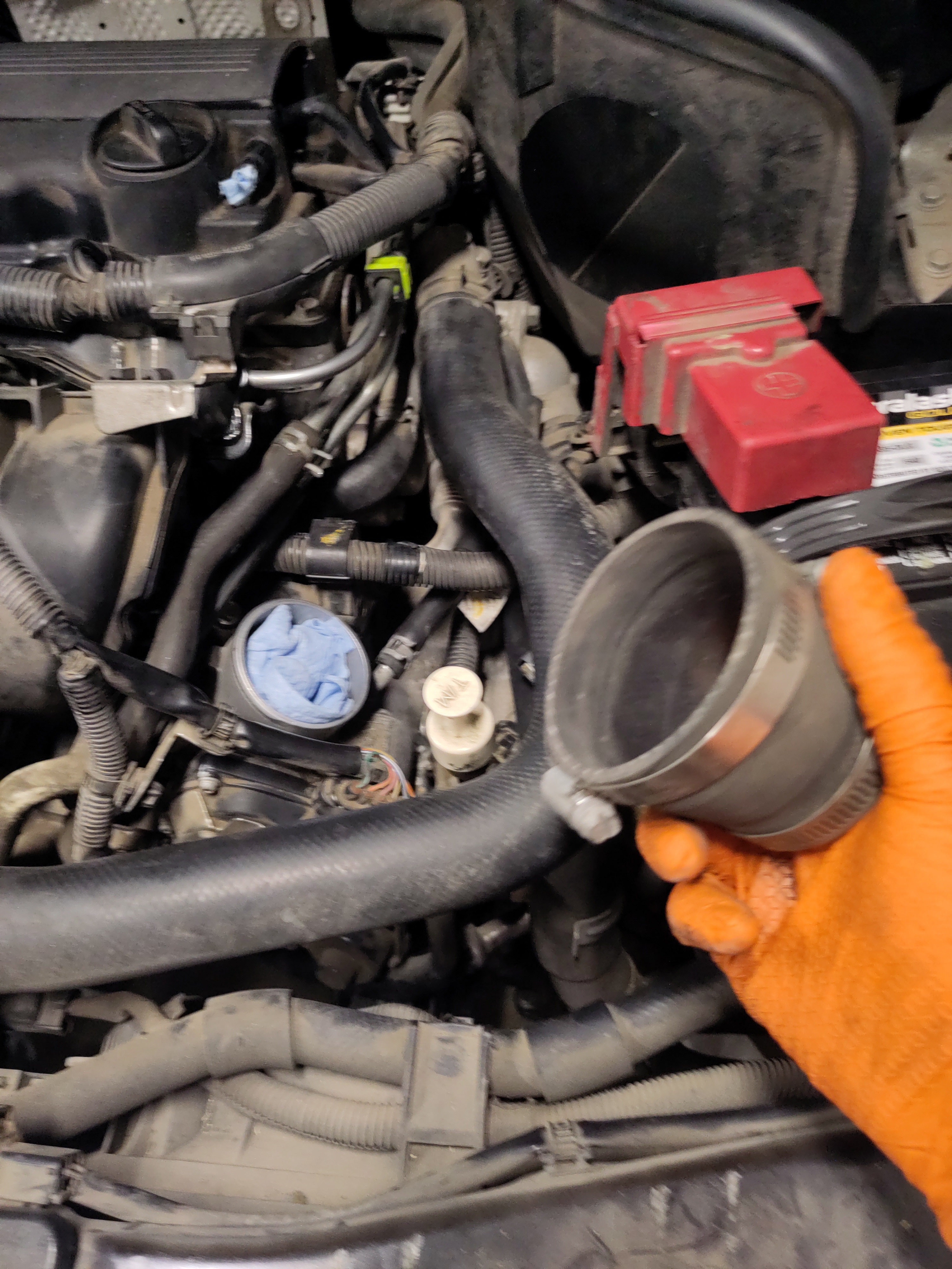
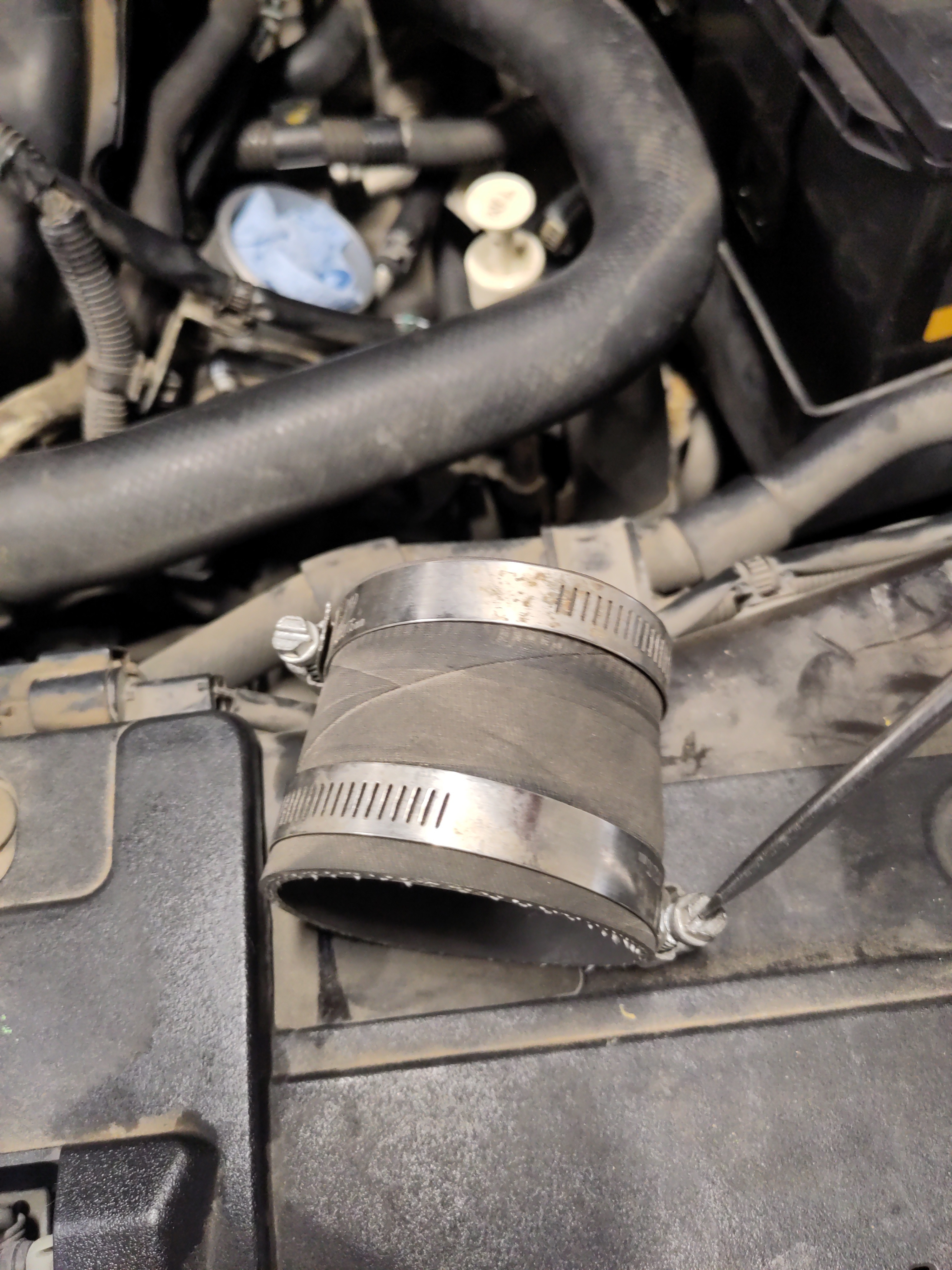
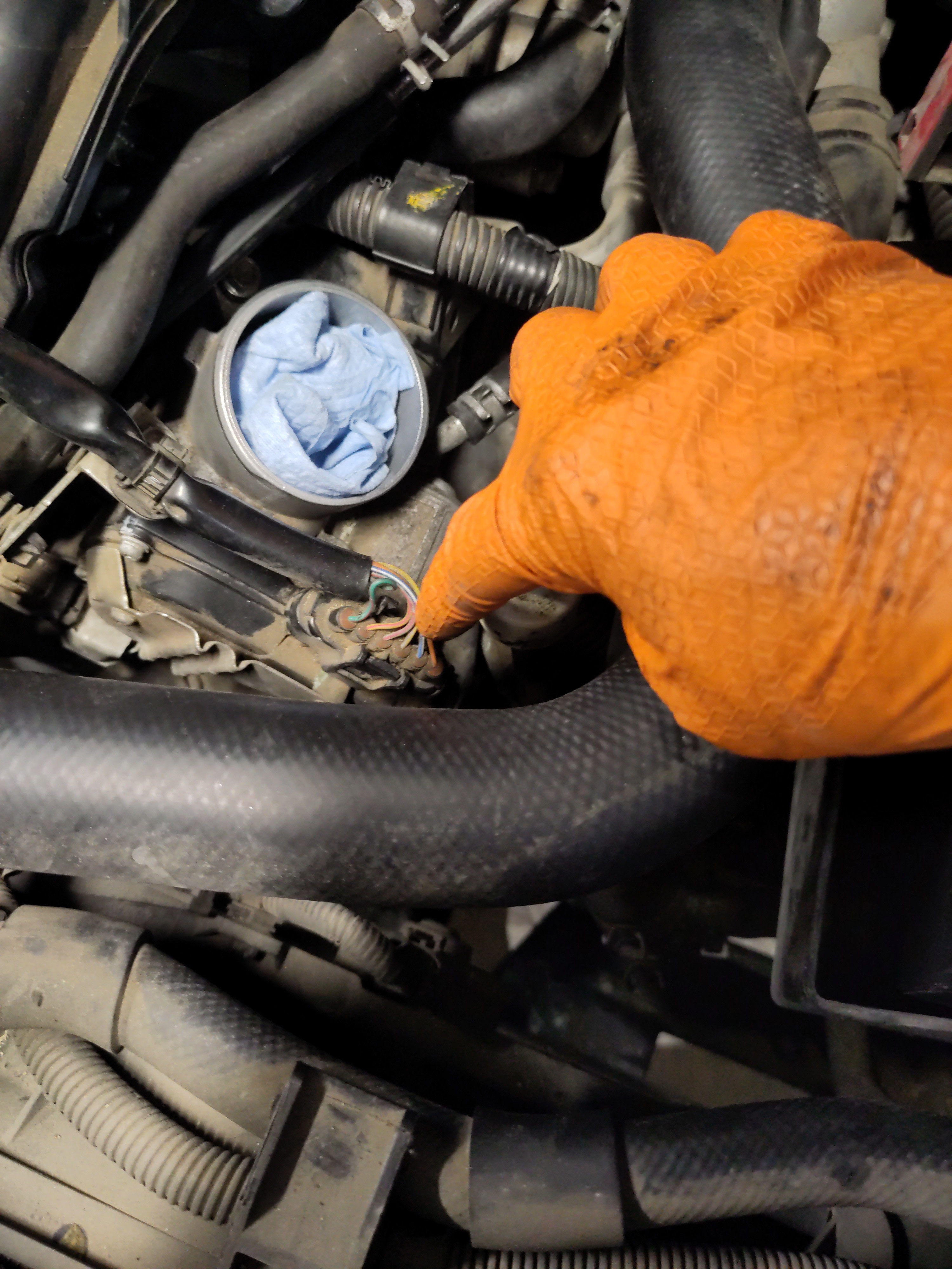
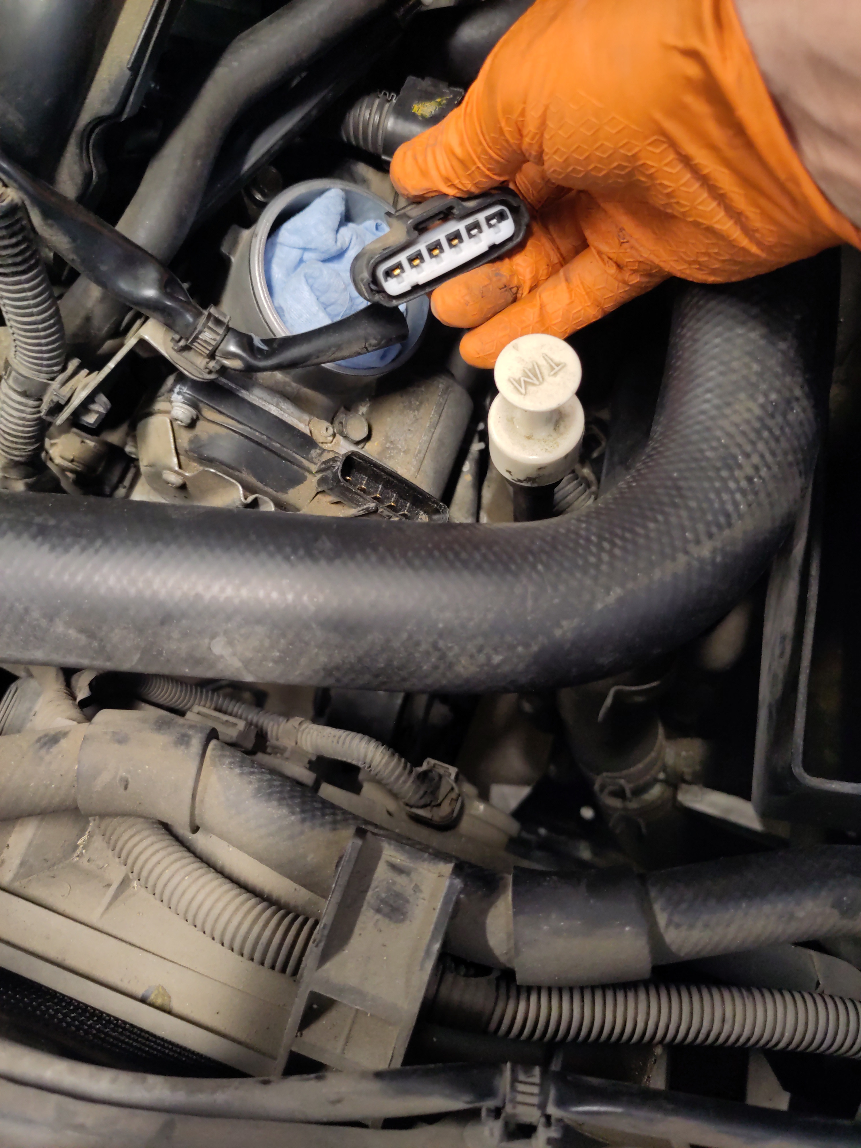
- The throttle body electrical connection will need to be disconnected and set off out of the way. Similar to disconnecting the mass air flow sensor. Push the pin in then pull up on it to remove it. It is important to put the male electrical connection end out of the way because in the next coming steps coolant will be getting drained out and want to prevent it from getting on the any electrical circuitry.
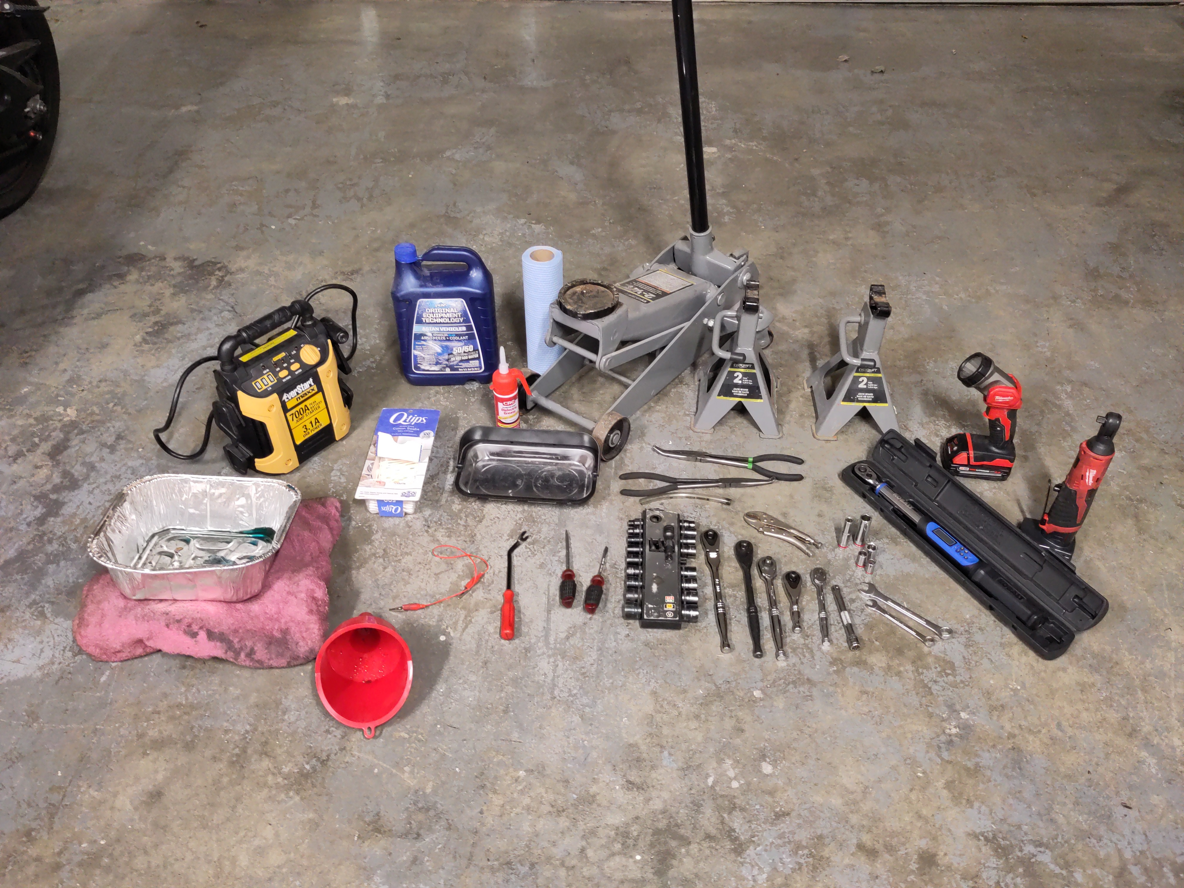
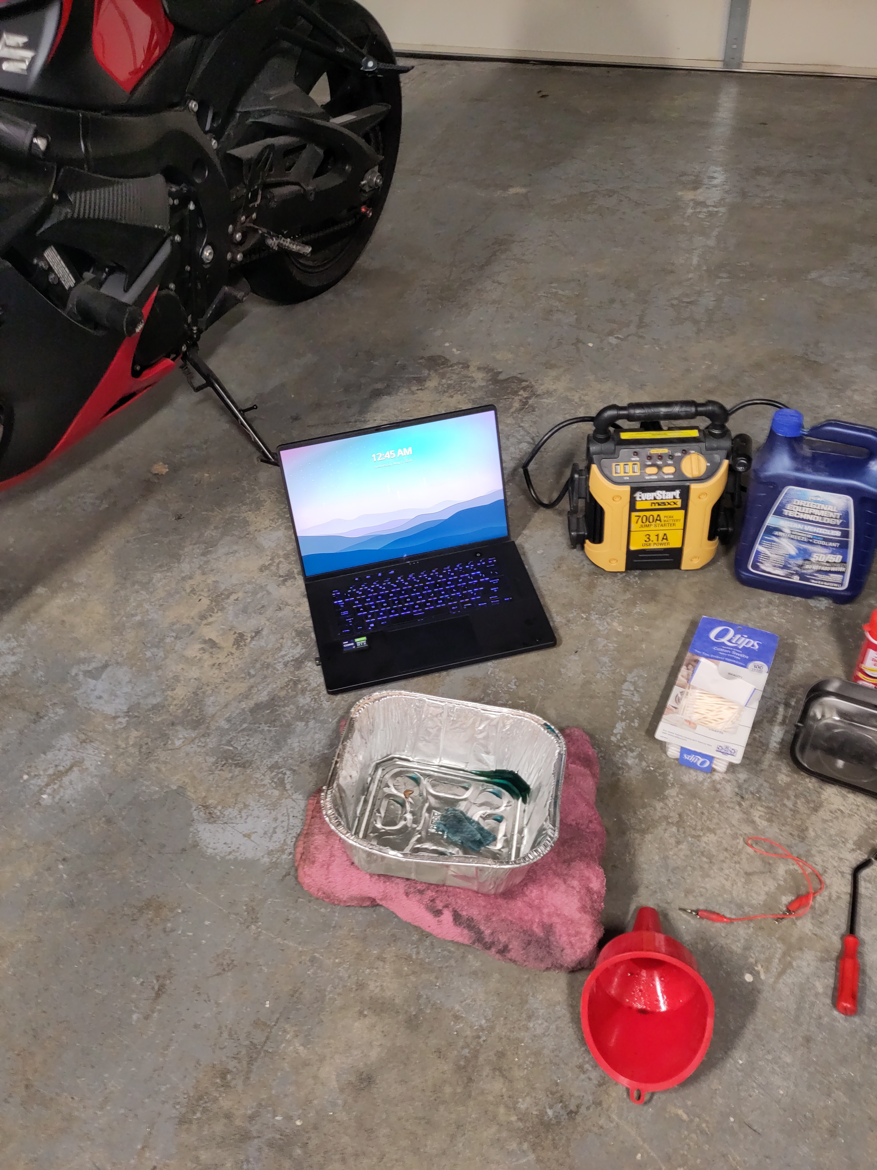
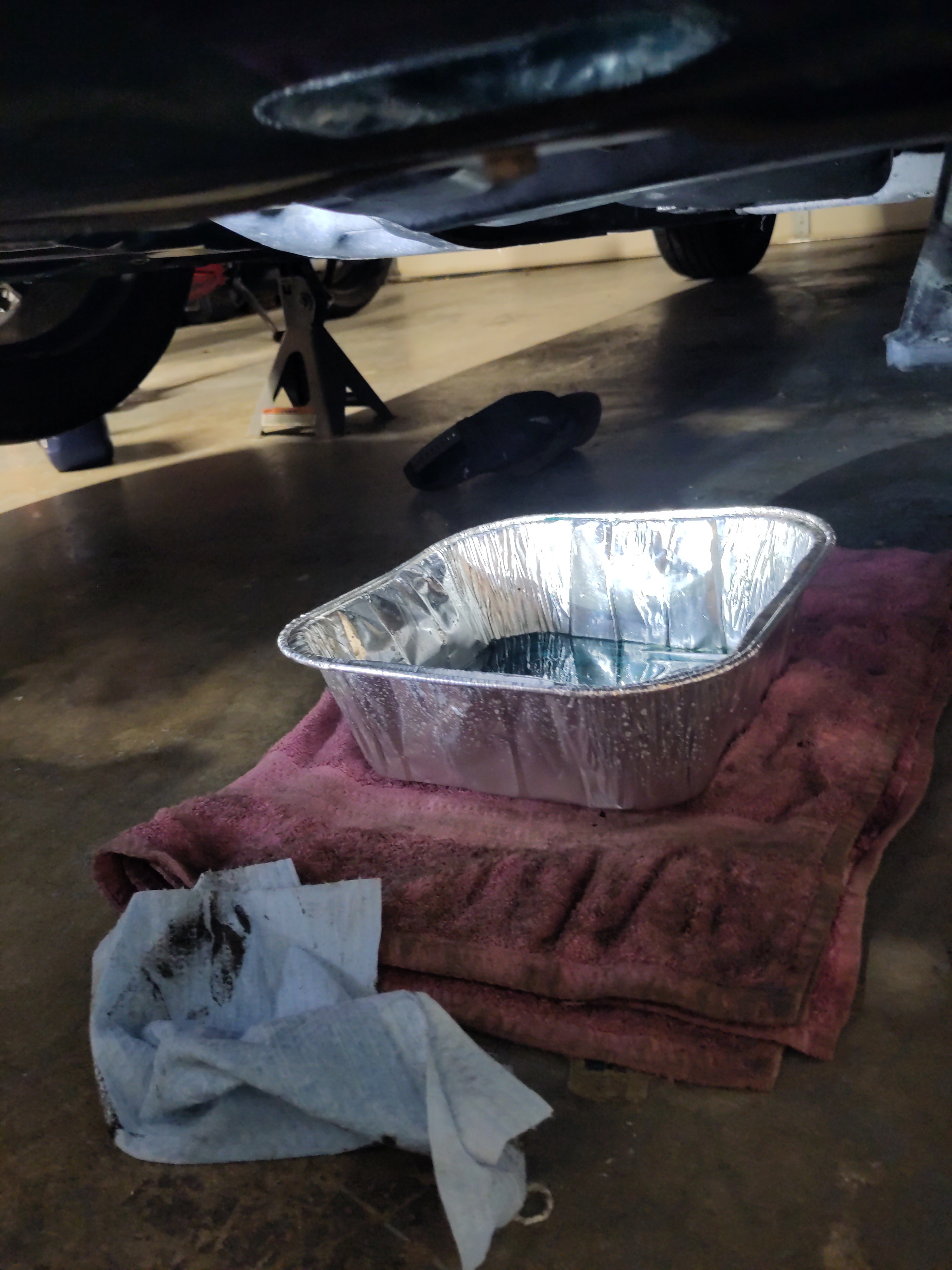
- Take the drip pan and the old towel and the placement of the them should approximately aligned with the throttle body. The drip pan and towel there to catch all coolant that will be leaking out for when we remove a coolant hose connection. Having a flash will beneficial to use at this point.

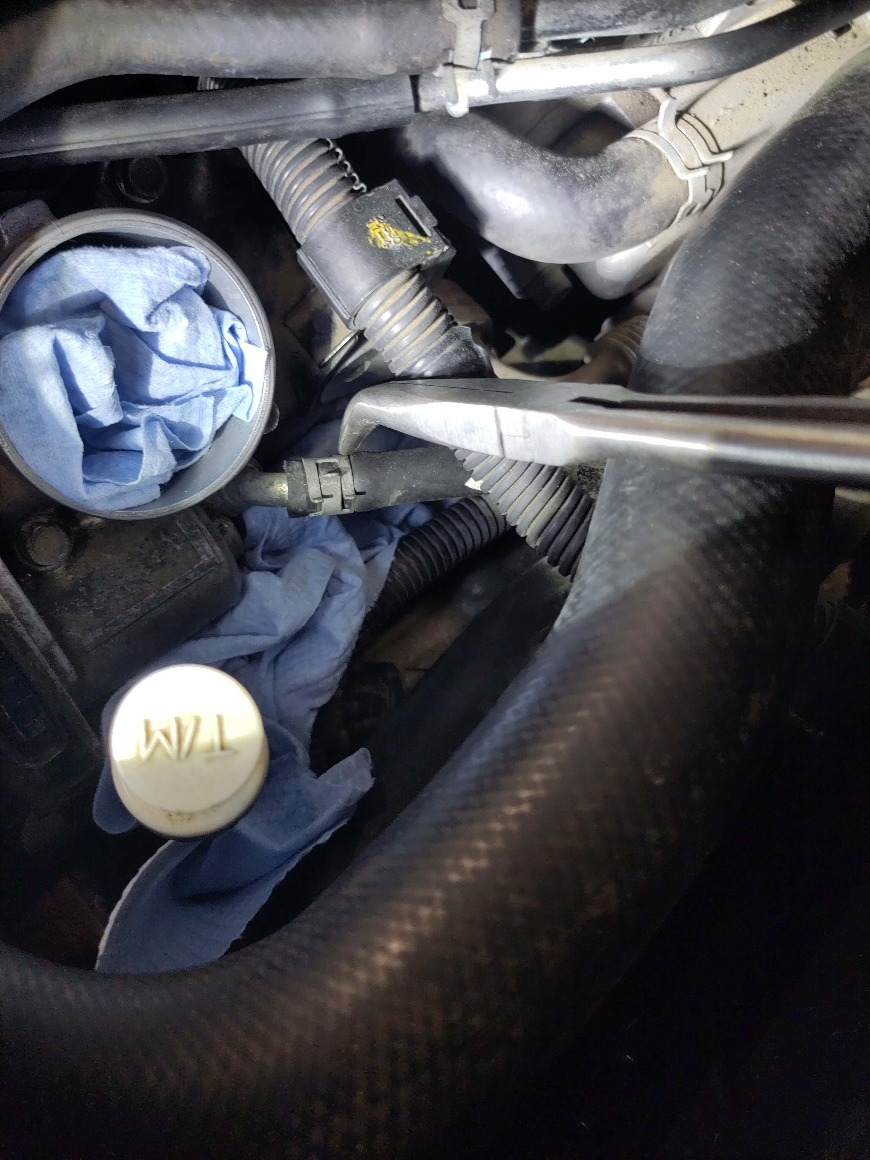
- Stuff paper towels or old rags into the crevices and gaps of the engine that are below the coolant hose in order to mitigate a mess or component damage. The hose clamp will be removed by using long reach bent needle nose pliers. Squeezing the nose pliers with the proper angling will aid in removing it. Once it is loose just slide it toward the male end of hose insertion(located on the throttle body) and let it set there.
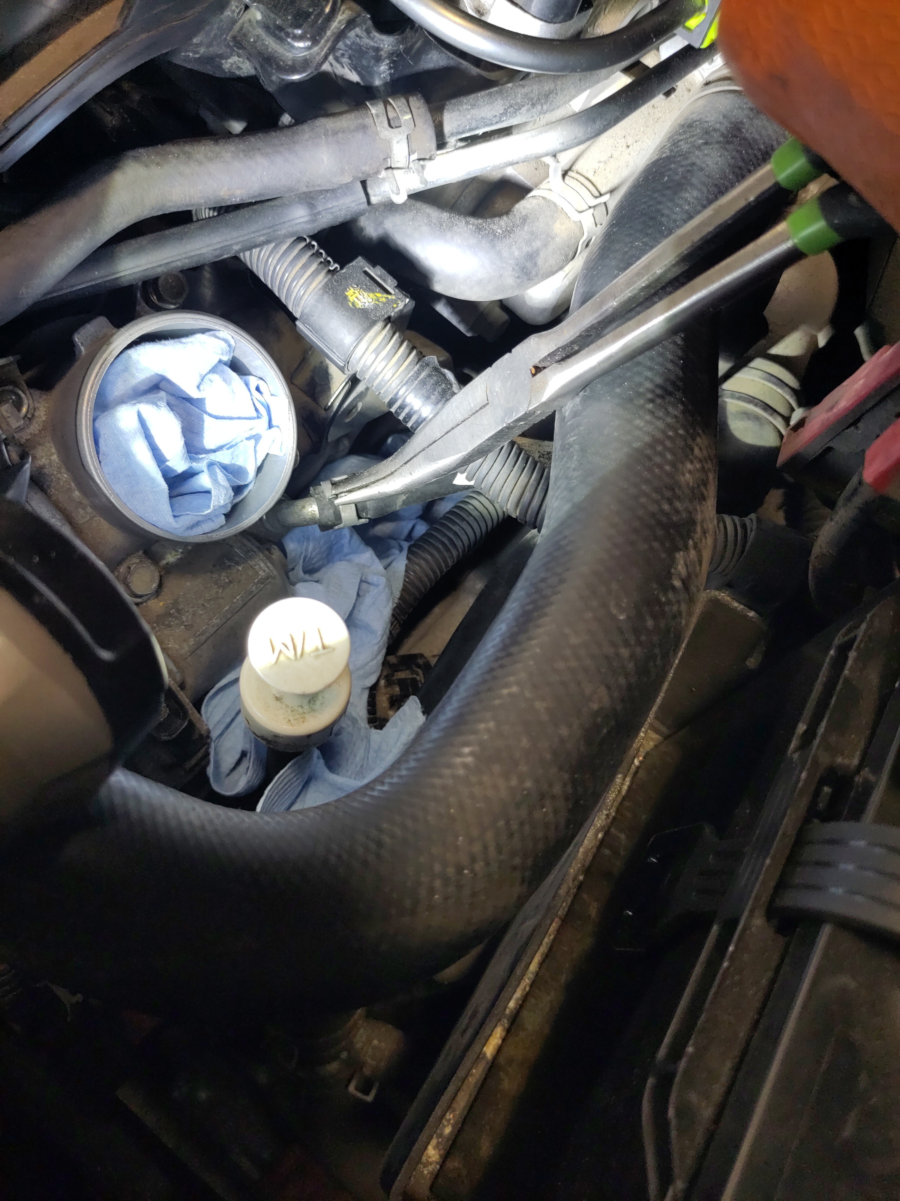
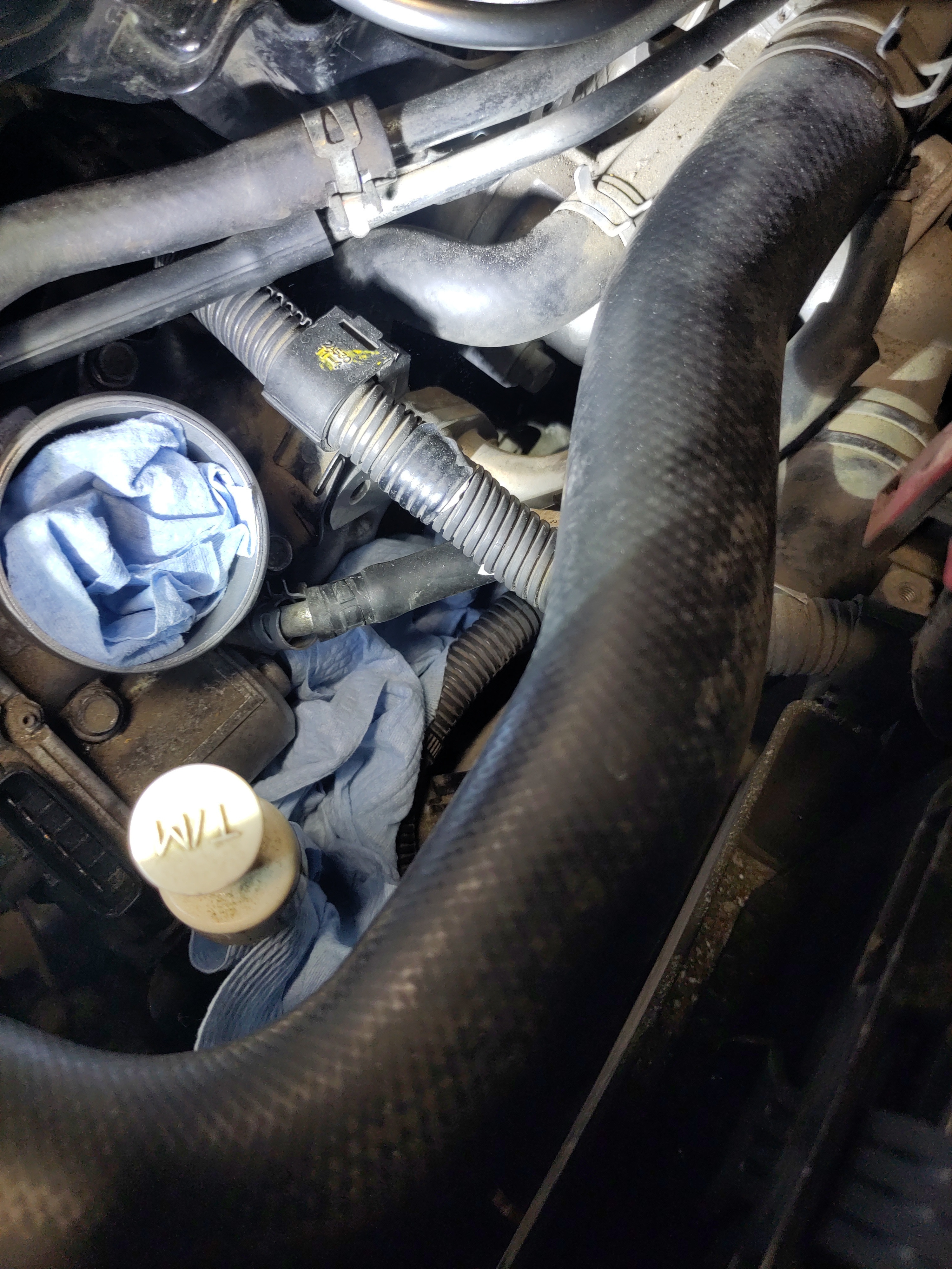
- Take the curved jaw locking pliers and place them upstream from the hose clamp the was removed from previous step. The locking pliers will help compressing the hose to create a flow blockage or at least slow the flow rate of the coolant down. Place the bent hose out the way and rip off a piece of a paper towel and insert into the hole to prevent debris or dust falling the hose.
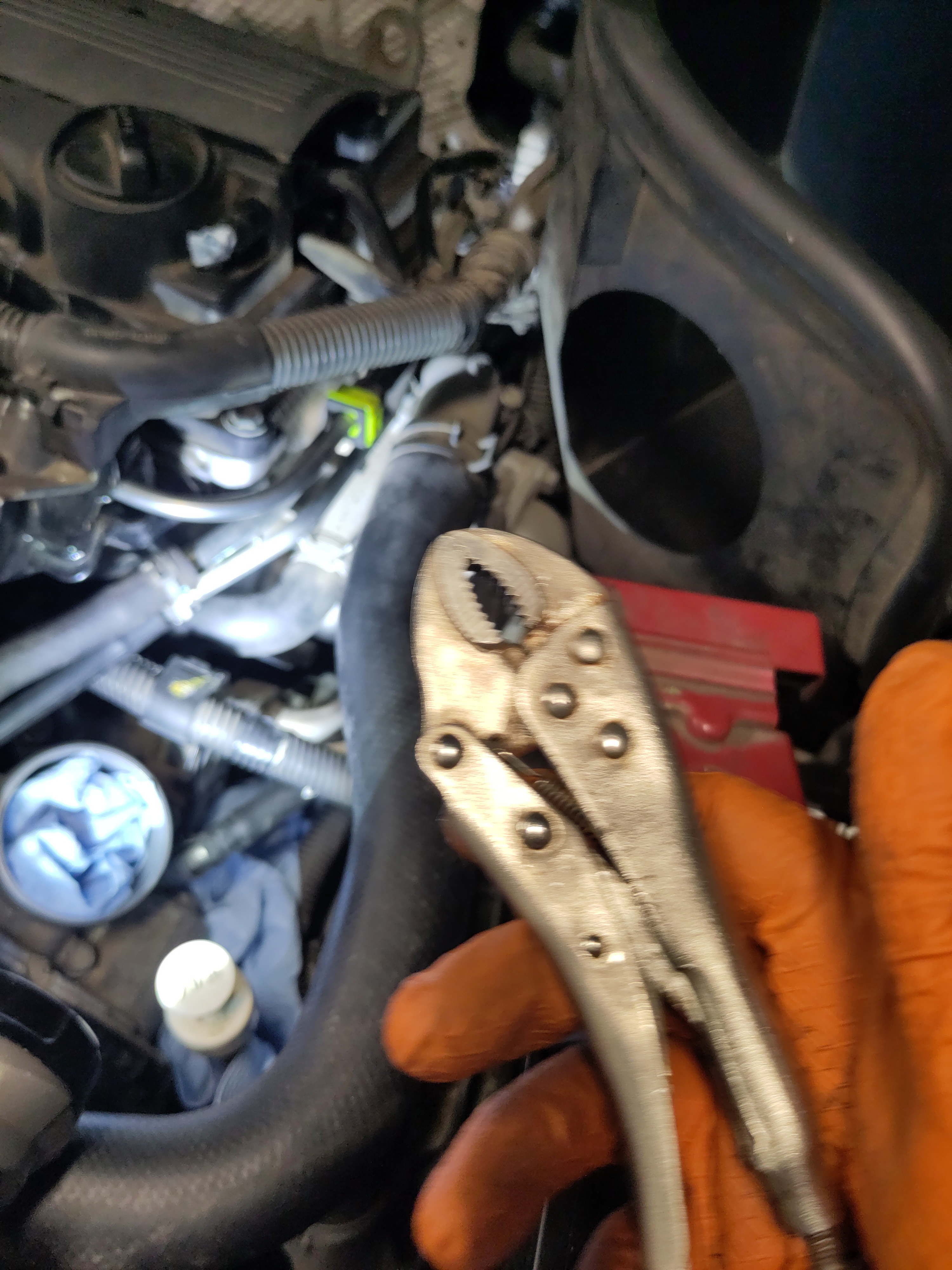

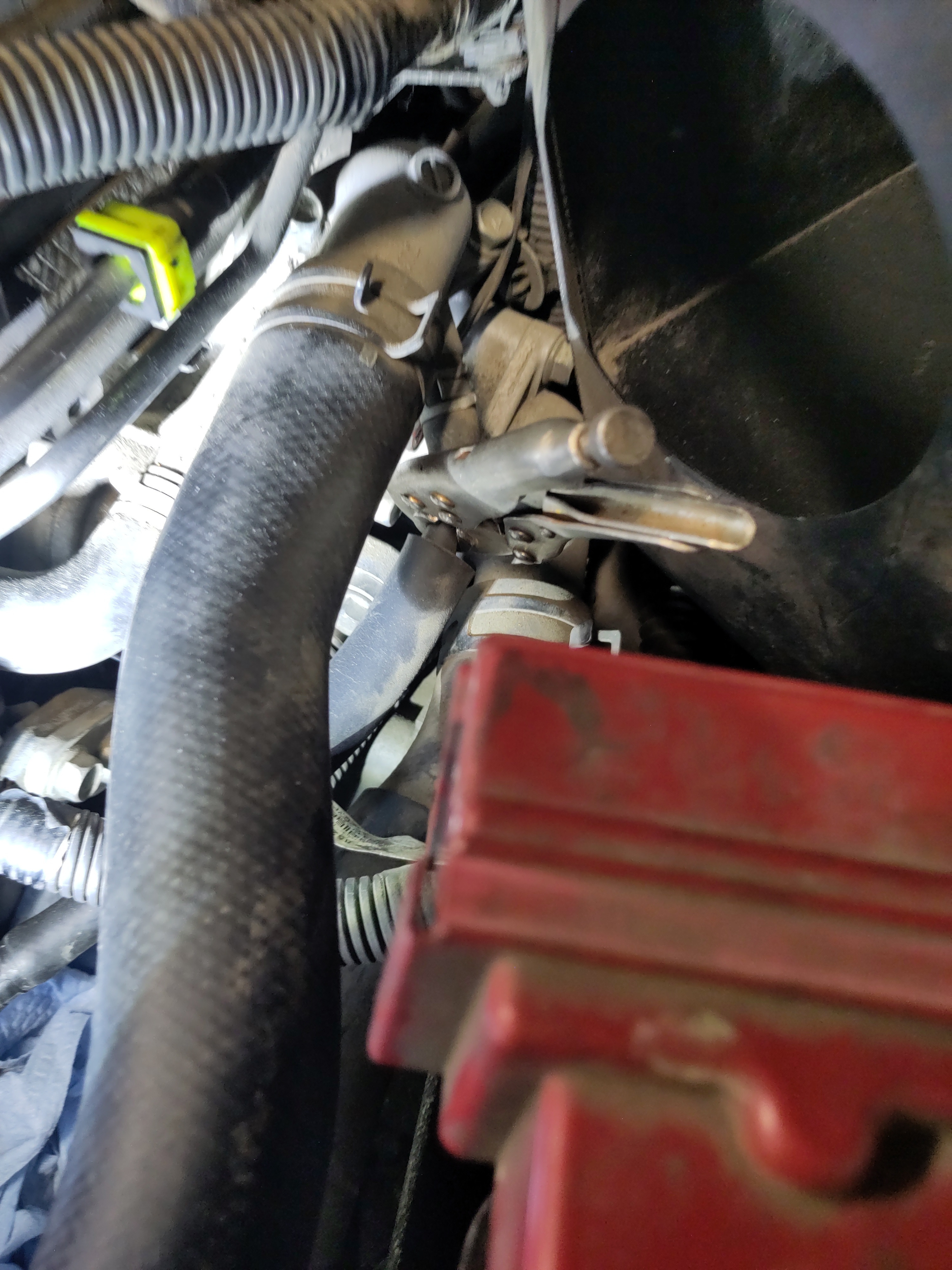
- Now try to wiggle the hose off the male end of the throttle body. It may be challenging to remove the hose so it necessary try using the small flat to pry of the hose by placing the the flat head in between the hose and the surface of the male end connection. Once, the hose is removed coolant will begin to flow out of the male end of hose connection. Using the 1/4" clear silicon hose, quickly pull it on top of the male end of the throttle body. If needed it cut into the edge to further expand the clear silicon hose if necessary. Then take some paper towel and stuff the open end of the 1/4” clear silicon hose.
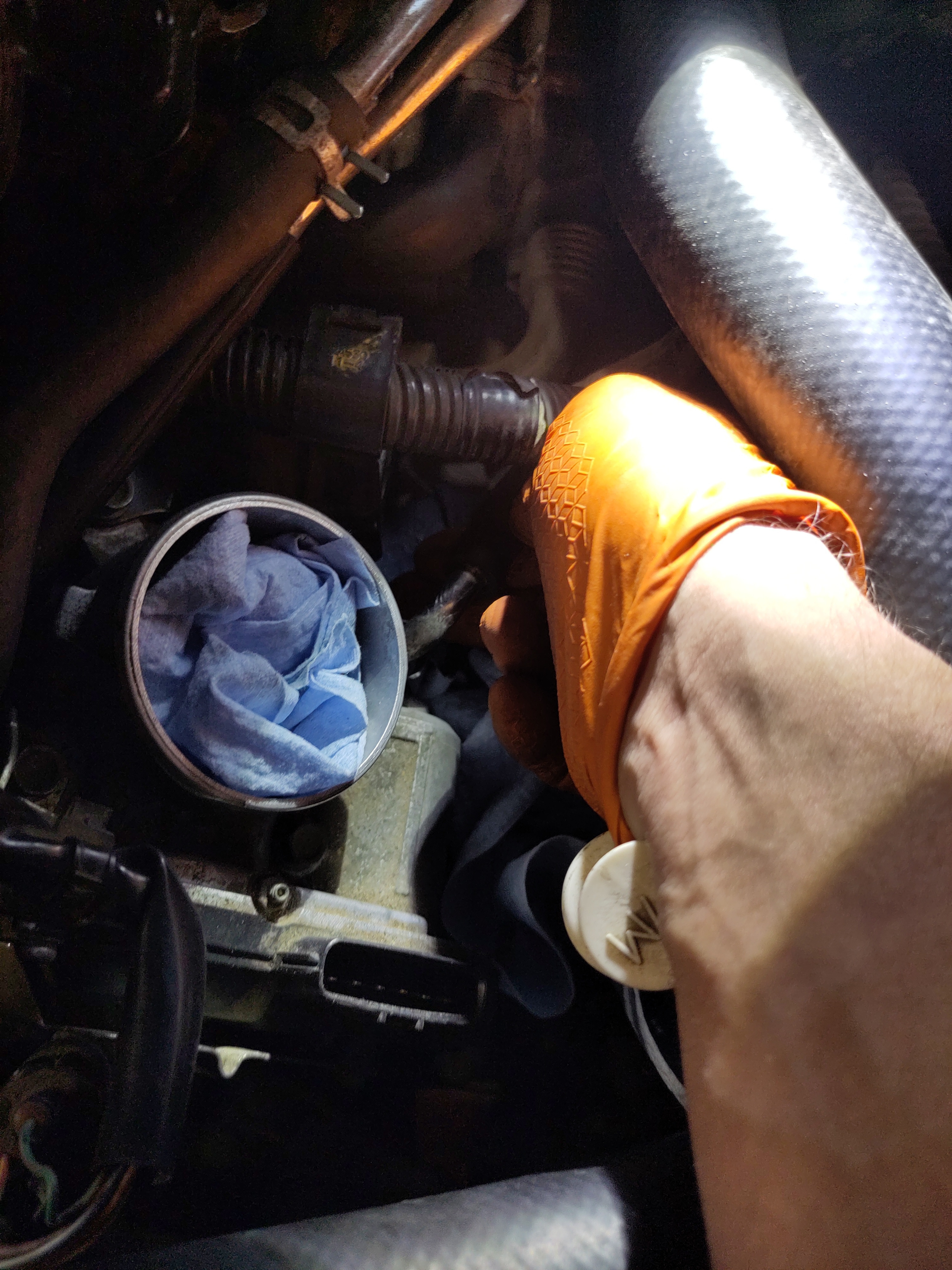
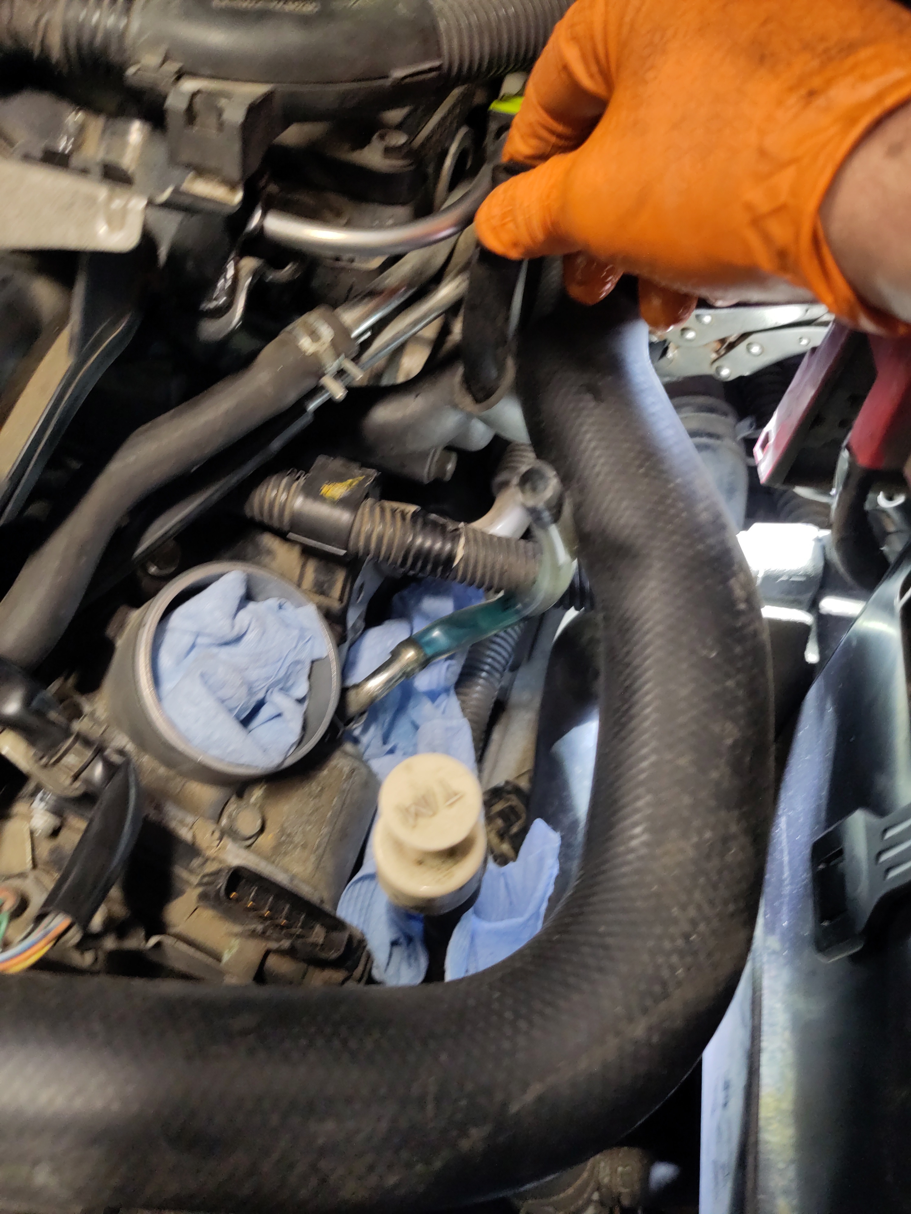
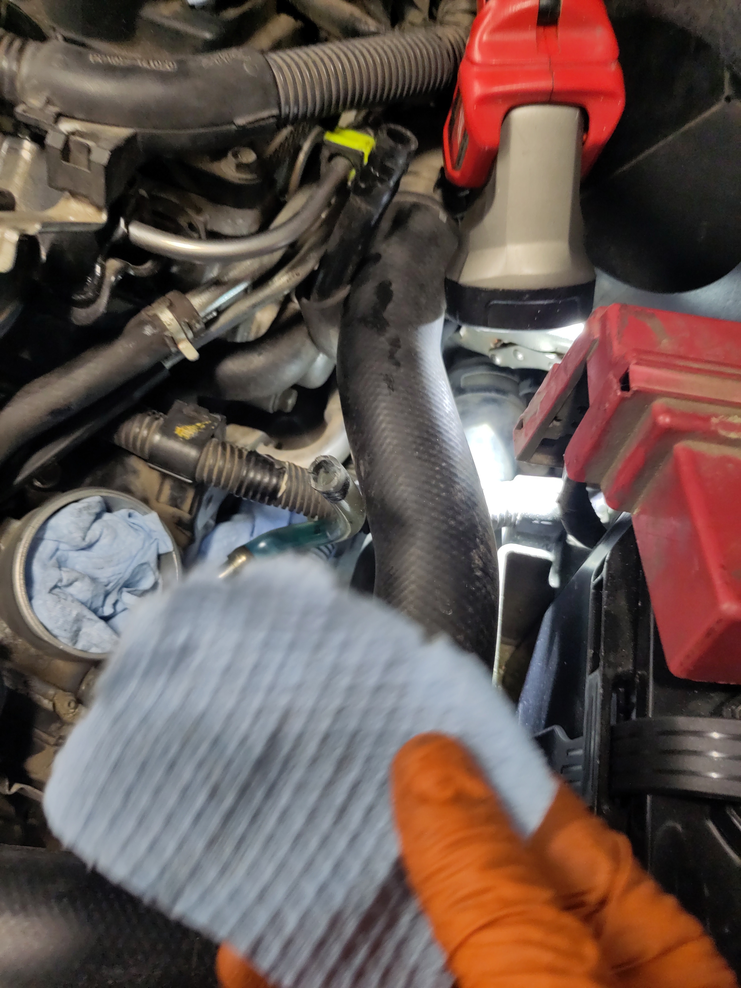
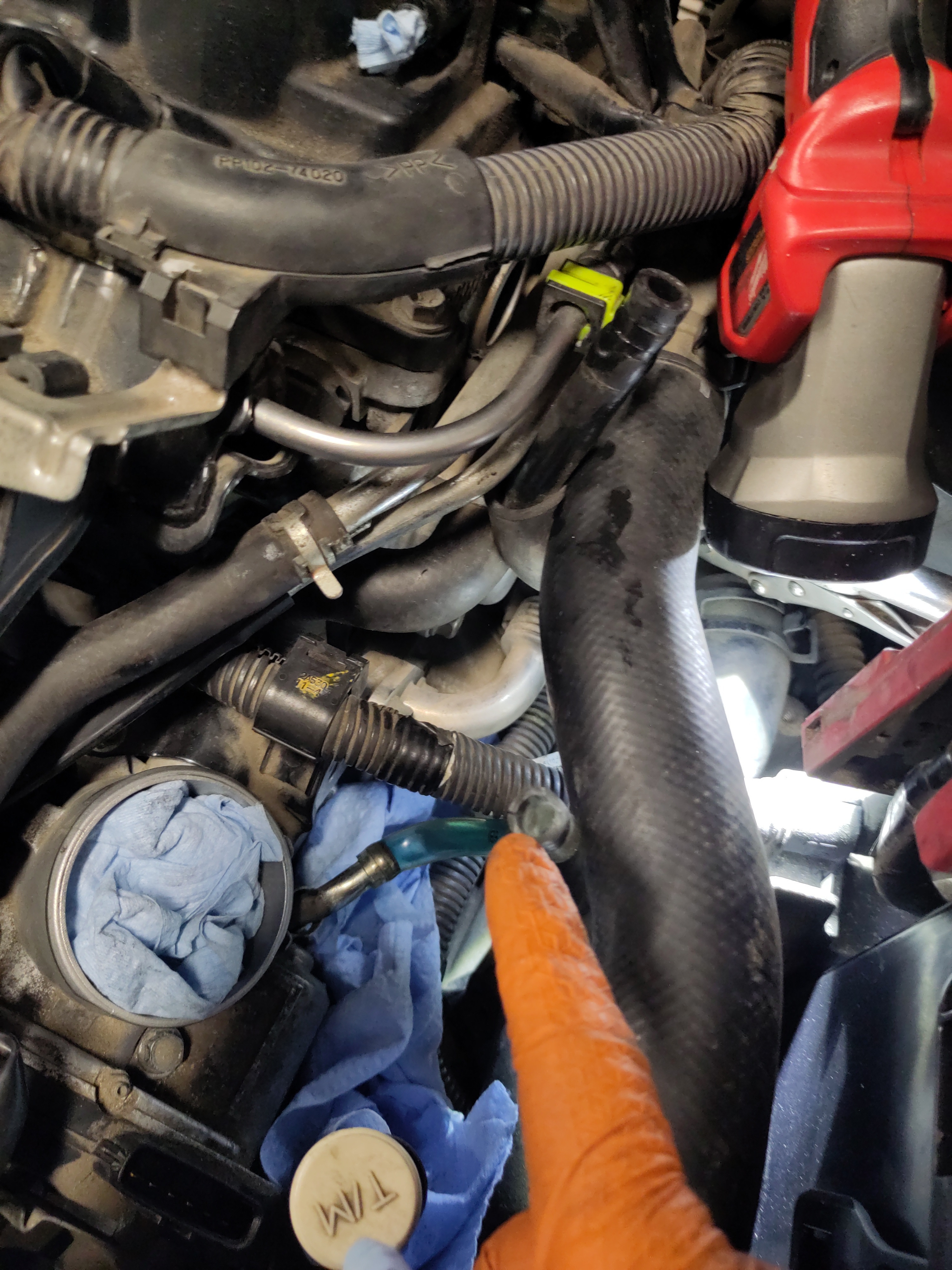
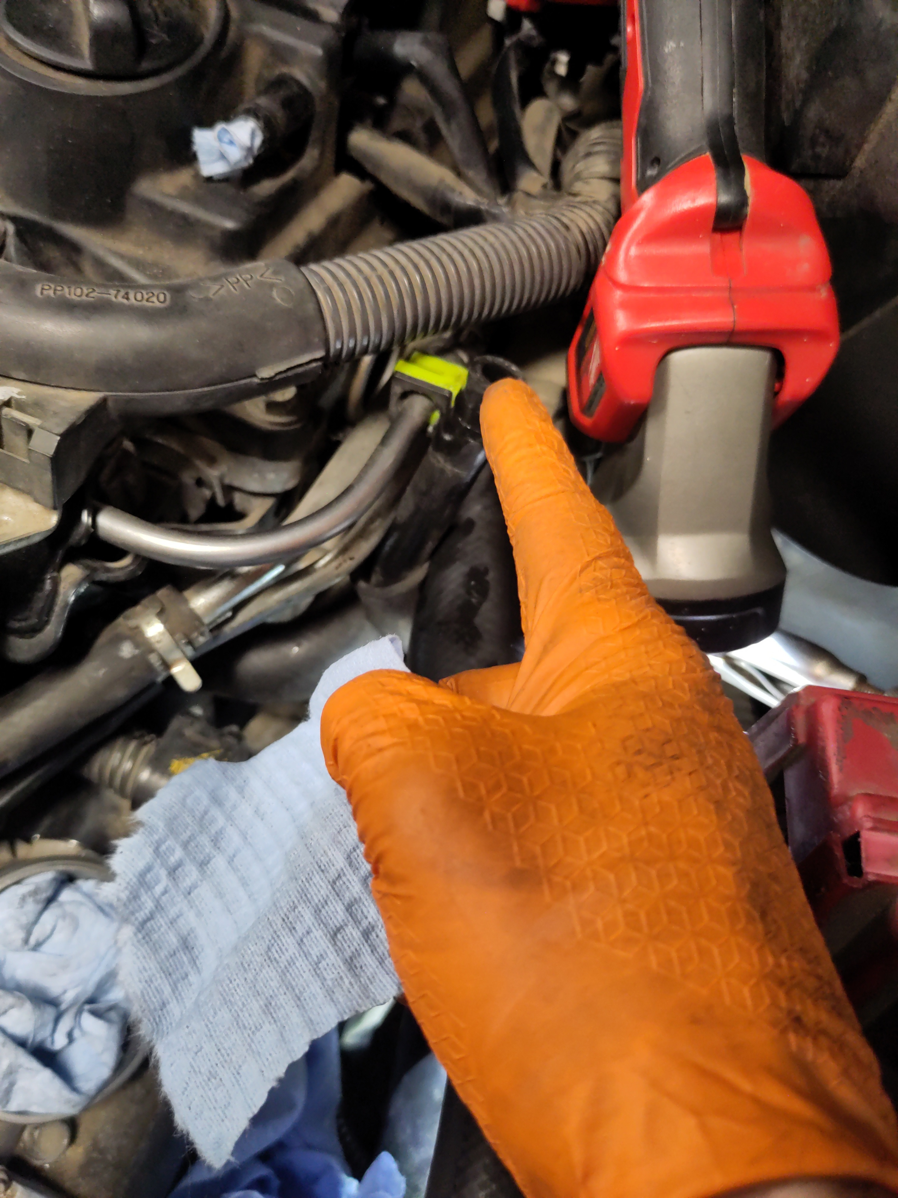
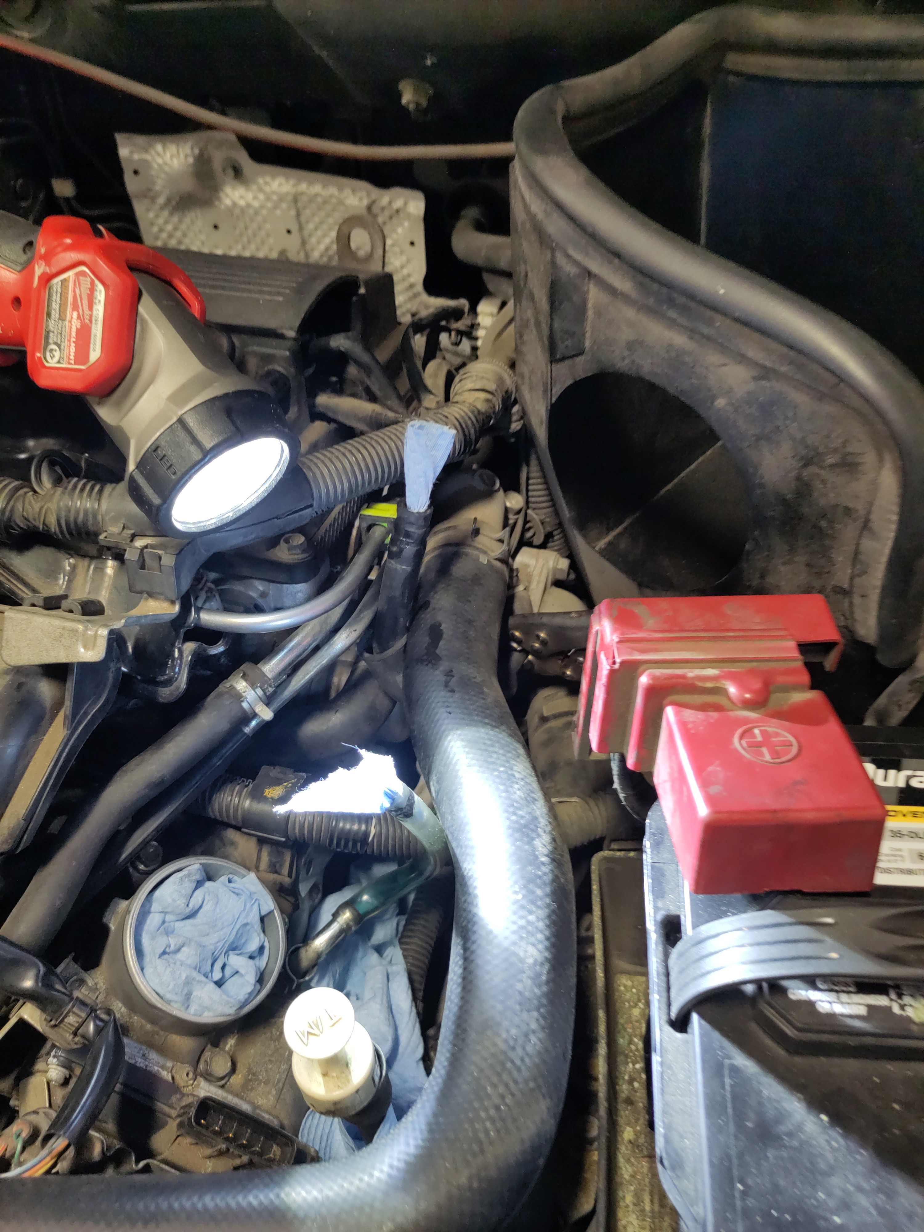
- OPTIONAL! There is a small diameter vacuum hose directly underneath a coolant hose. Both hoses are located above throttle body. The hose can be pulled off with ease, there no fasteners on such as a hose clamp securing the hose to the male end. Once the vacuum hose is pulled off, proceed to ripping two small pieces of a paper towel off. The placement of the to small pieces of paper towel will be inserted into the female end of the hose and the male end. The removal of the vacuum hose is ideal if needing to make it more accessible to reach the starter electrical connections which will happen later on.
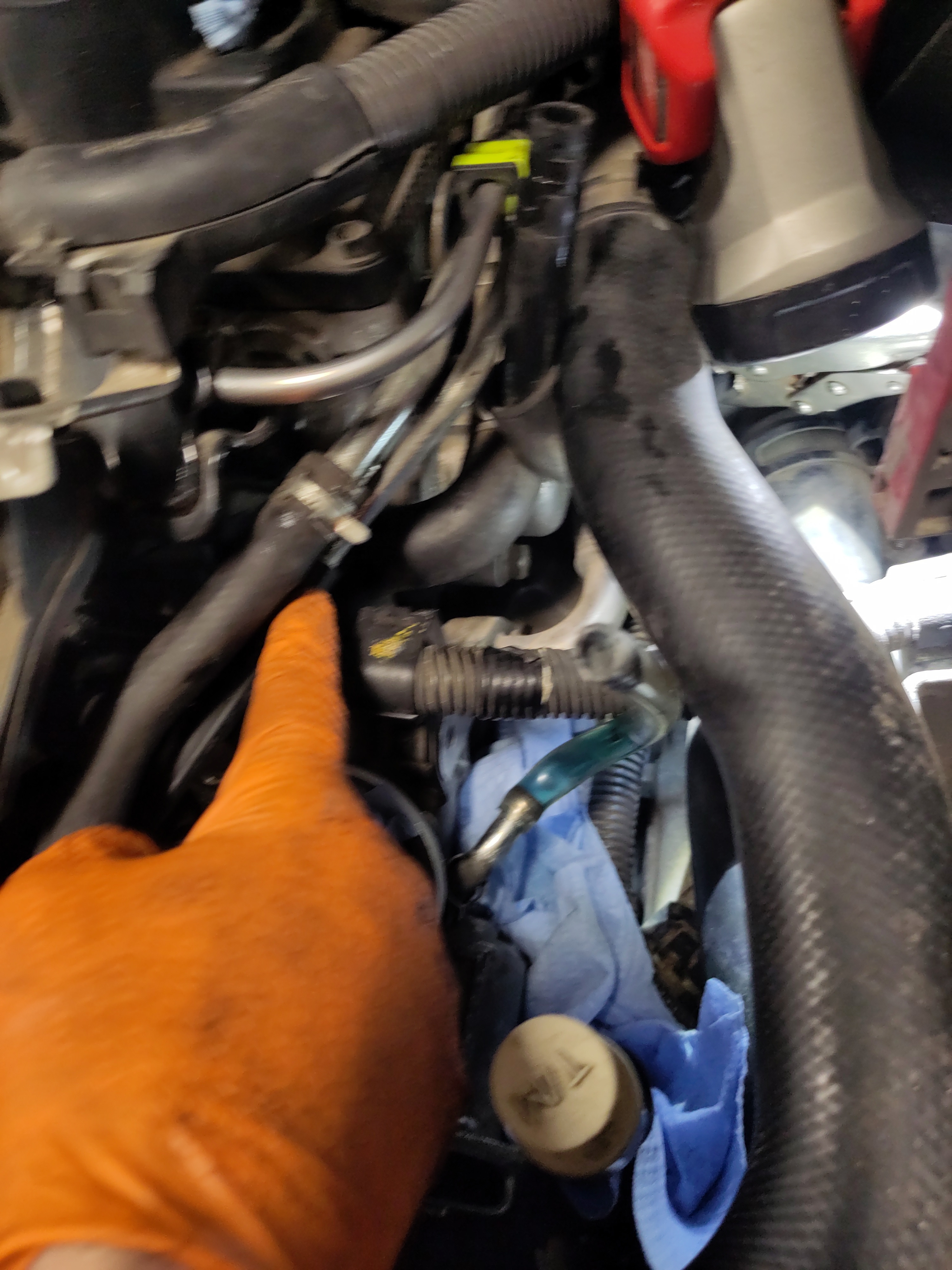
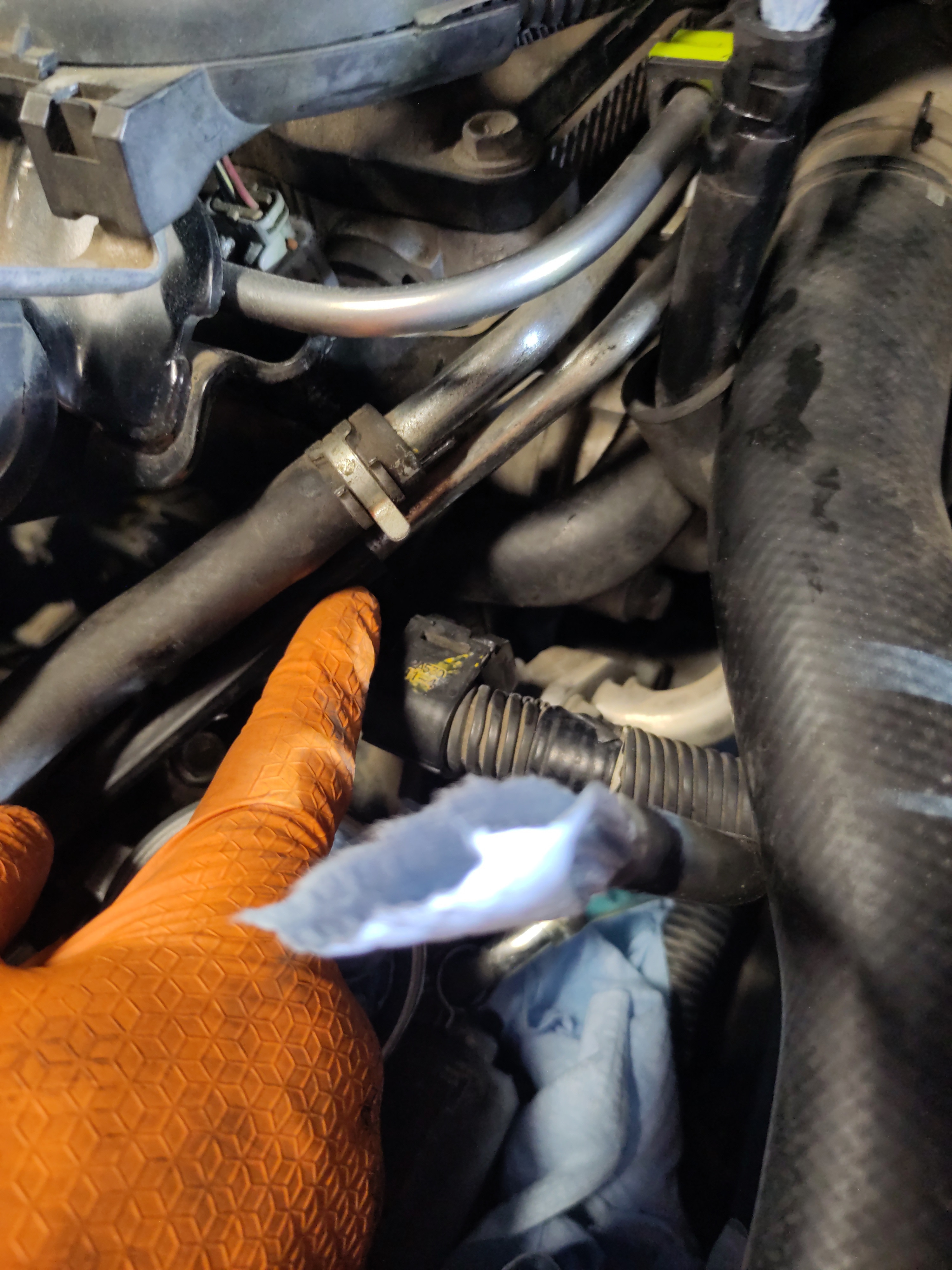
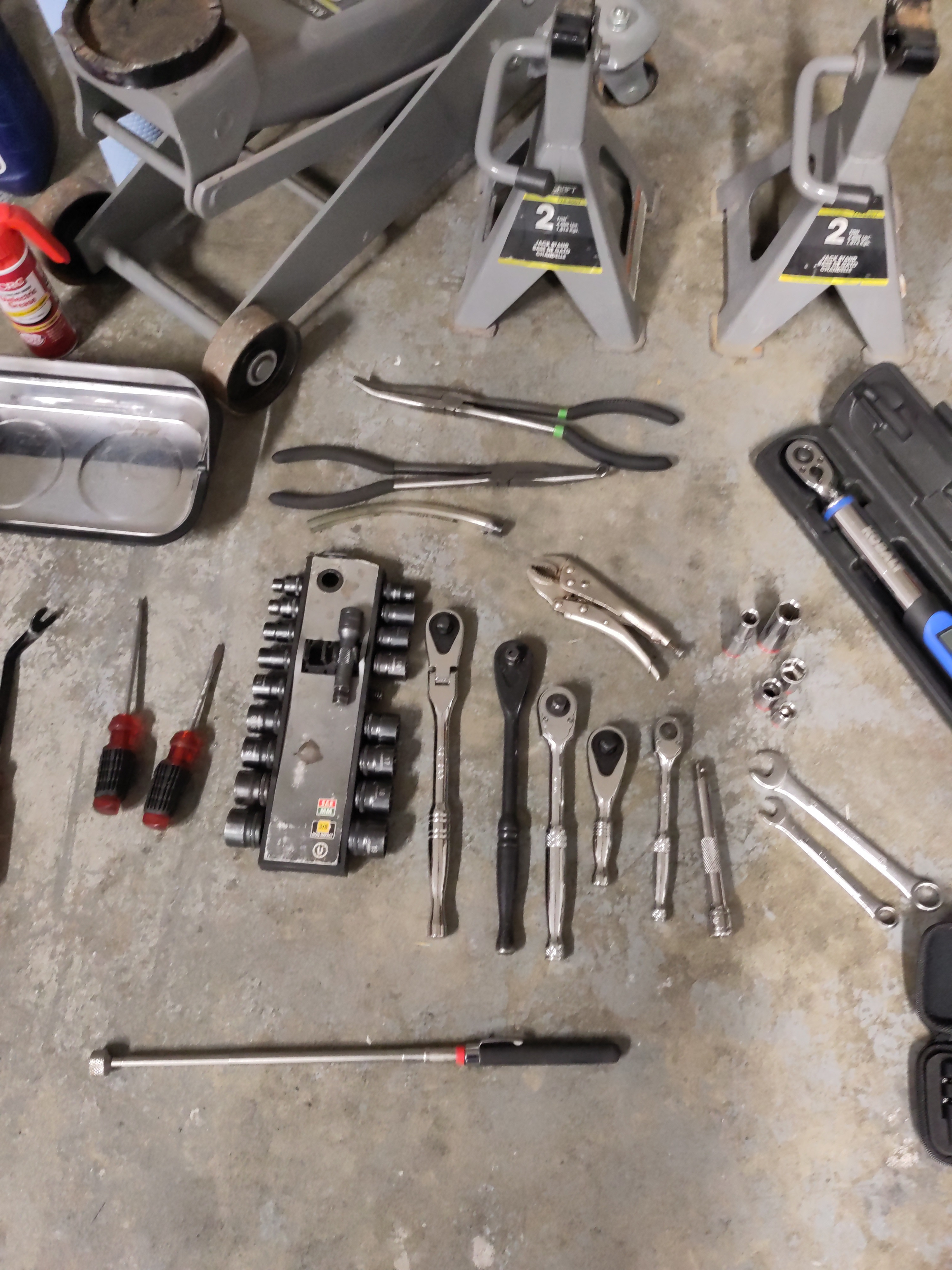
- Now to it is time to uninstall the throttle body, but we will not fully remove it just siding it towards you and having it rest up on the coolant hoses and radiator. So the two bolts holding in the starter can be accessible. There are four 10mm bolts securing the throttle body to the engine. 3 of the 4 bolts are holding in place wire hangers/ organizers. It is easy to remove the wire, but I found it easier just to remove it all assembled and place it out of the way. Recommendation, is to use a deep 10mm 6 point point with a 3/8" drive socket wrench with an extension to undo each 10mm bolt. Put the 4 throttle body bolts in the magnetic pan for safe keeping.
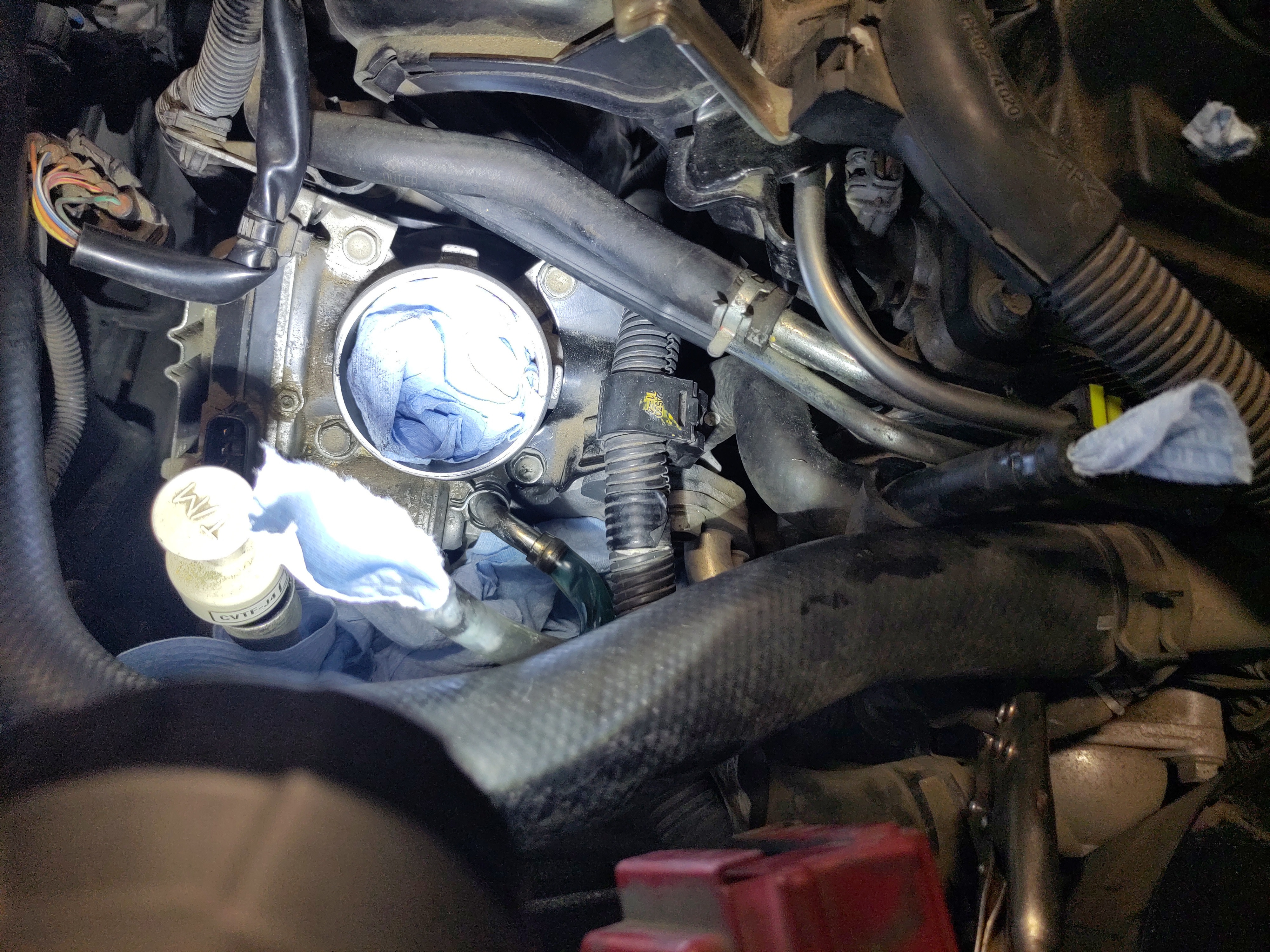
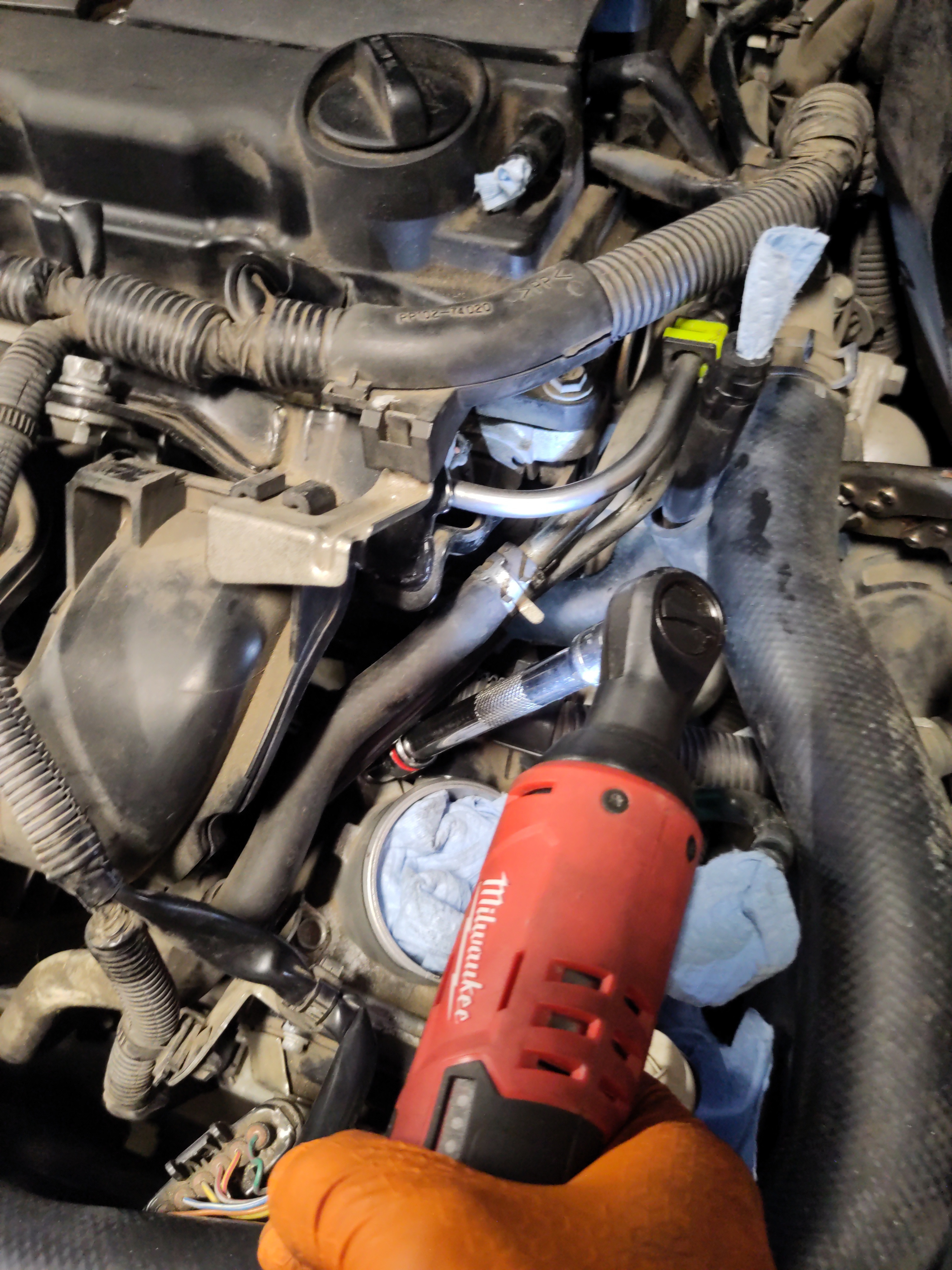
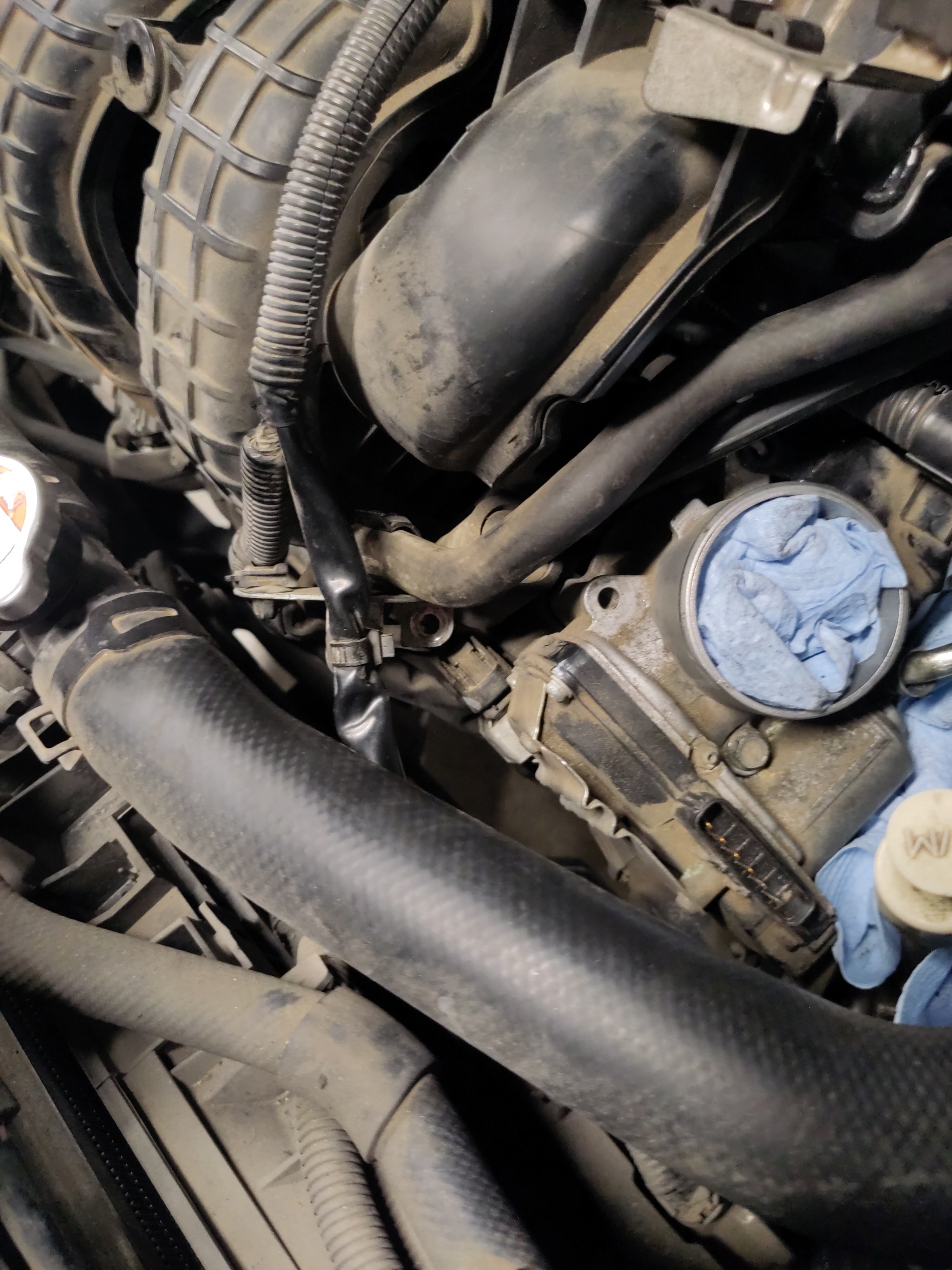
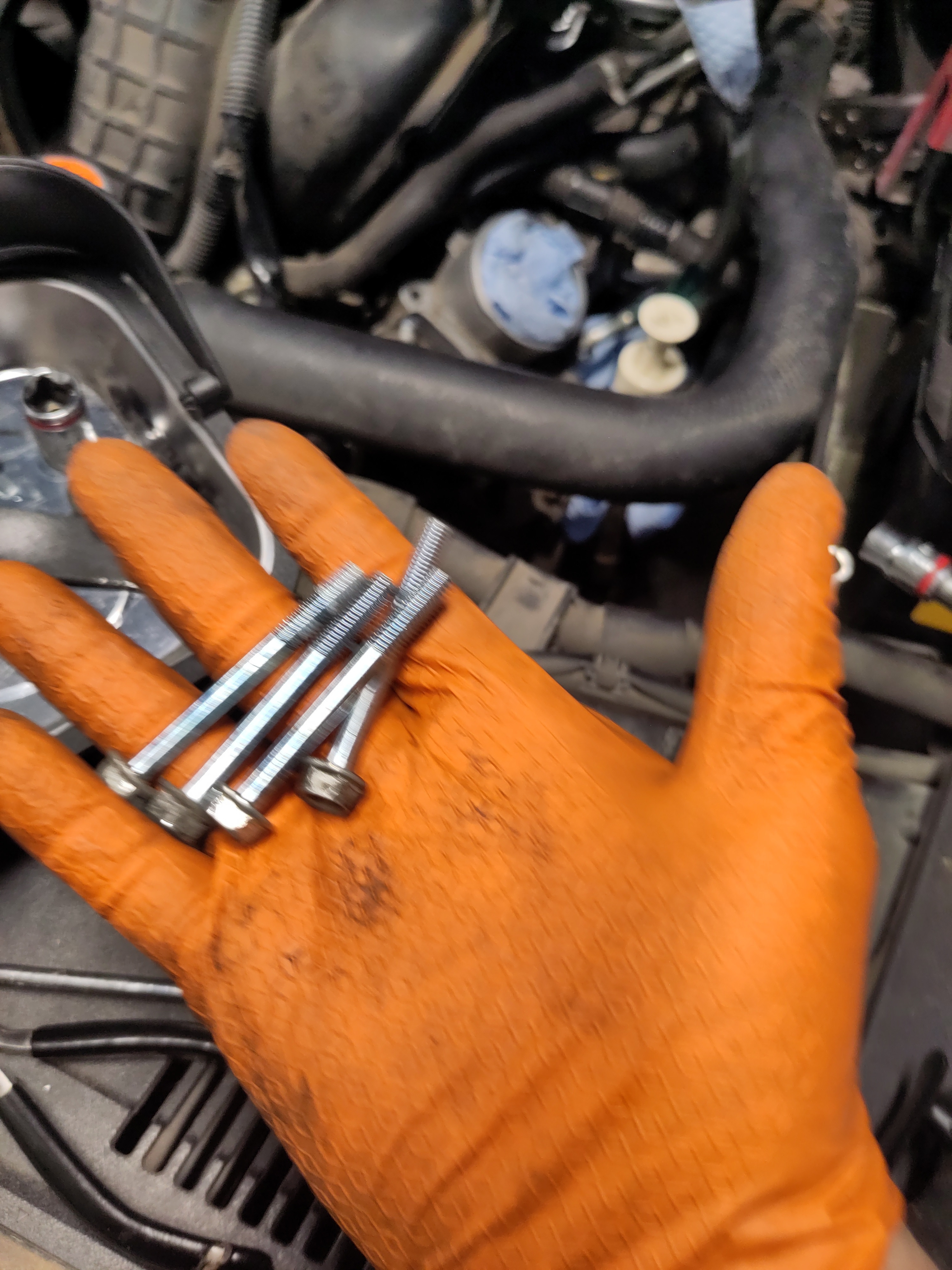
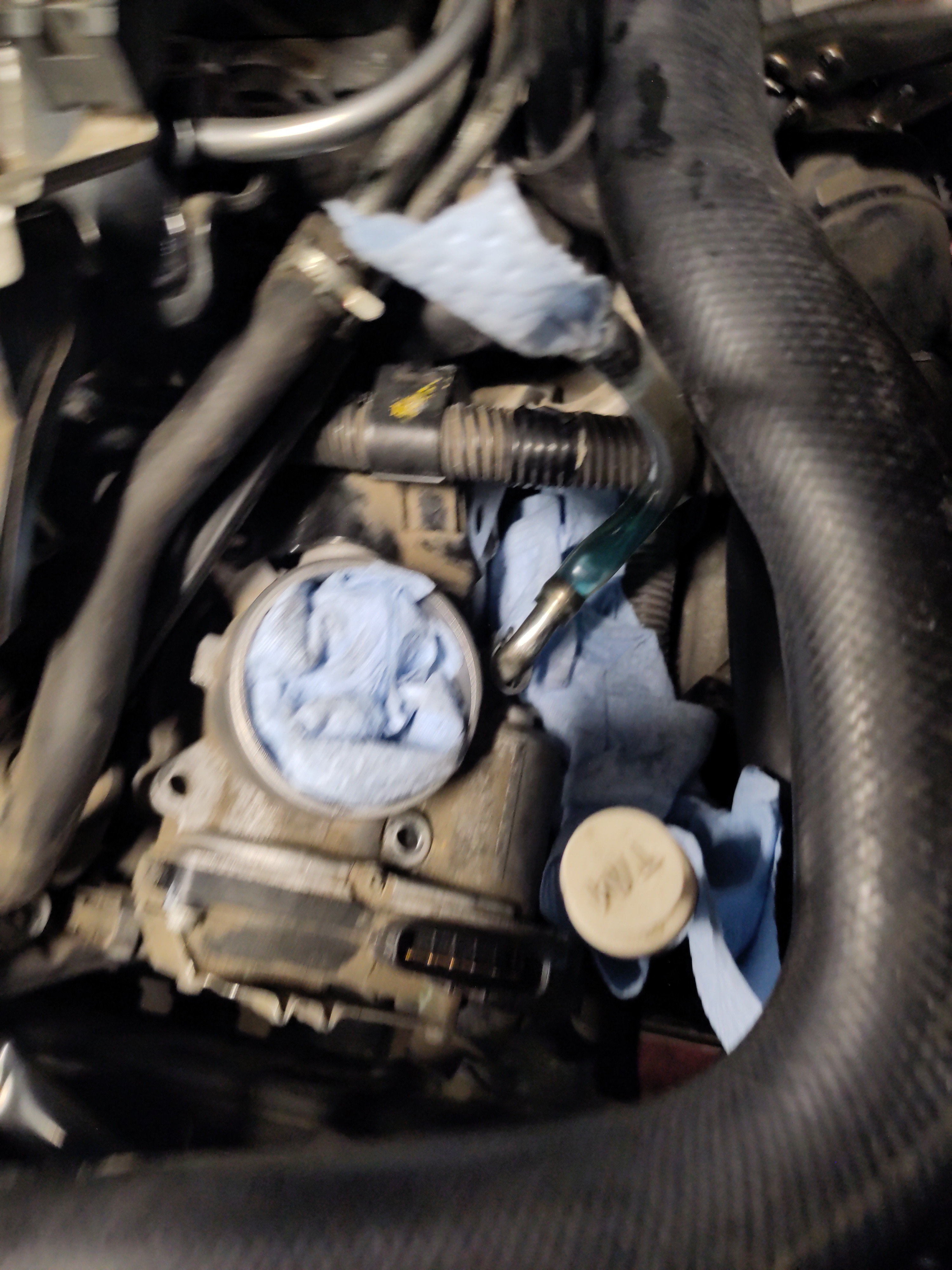
- Now move the throttle body towards you and place it underneath the coolant hose and have it properly rested on some of the components. The placement is crucial because if placed wrong coolant may flow out of the 1/4" diameter clear hose. So placing the throttle body underneath the coolant hose and resting partially on the radiator and the fan, it seat snug and didn't impact the job.
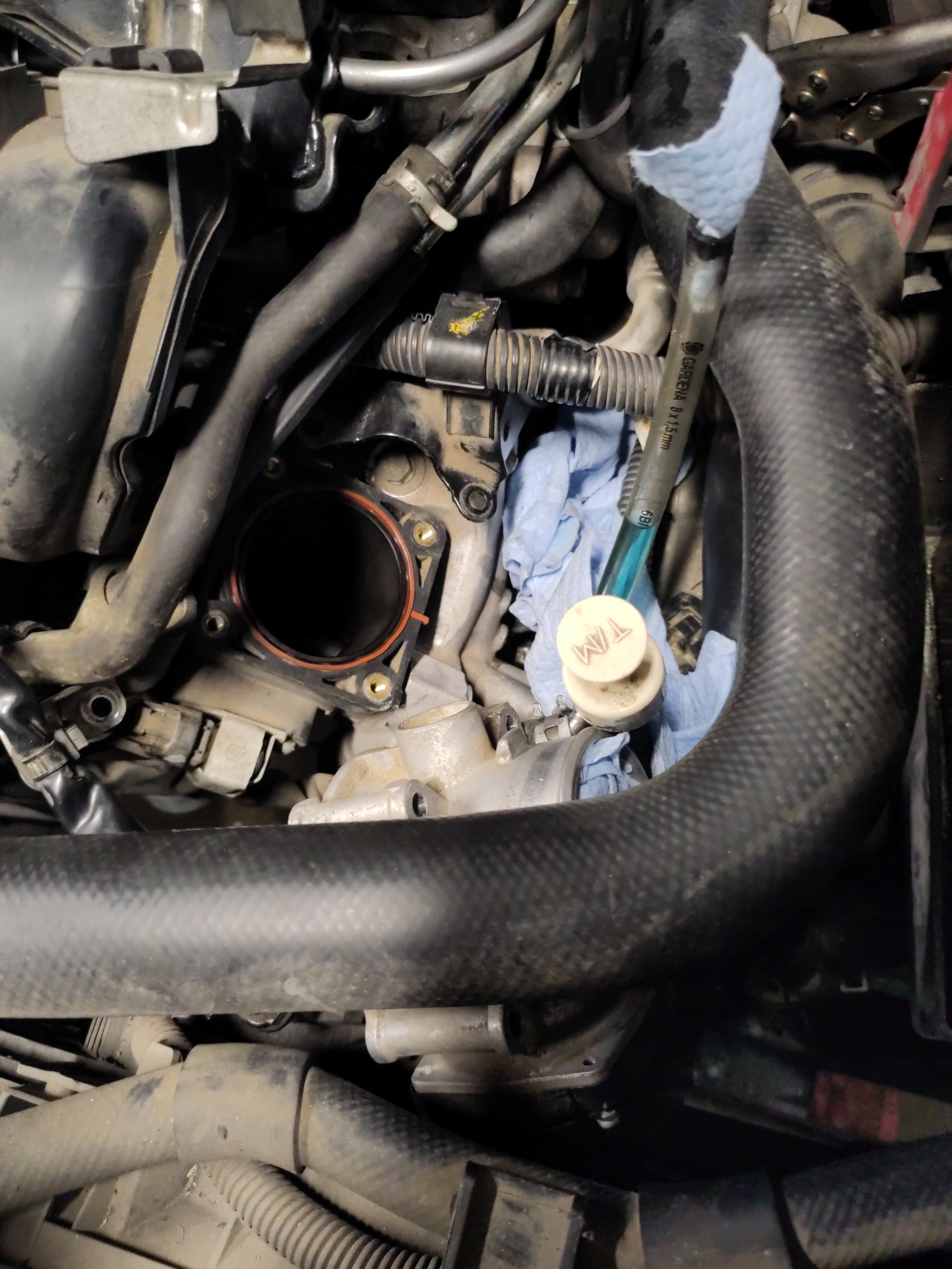
- Once the throttle body is out of the way, take a paper towel and place it into the entry way from what the throttle body was seated onto. It is also a good idea to wipe the surrounding area and the inside area with a clean paper towel just to remove any debris. Then insert the paper towel into the entry way to prevent dust or any other debris from entering the engine.
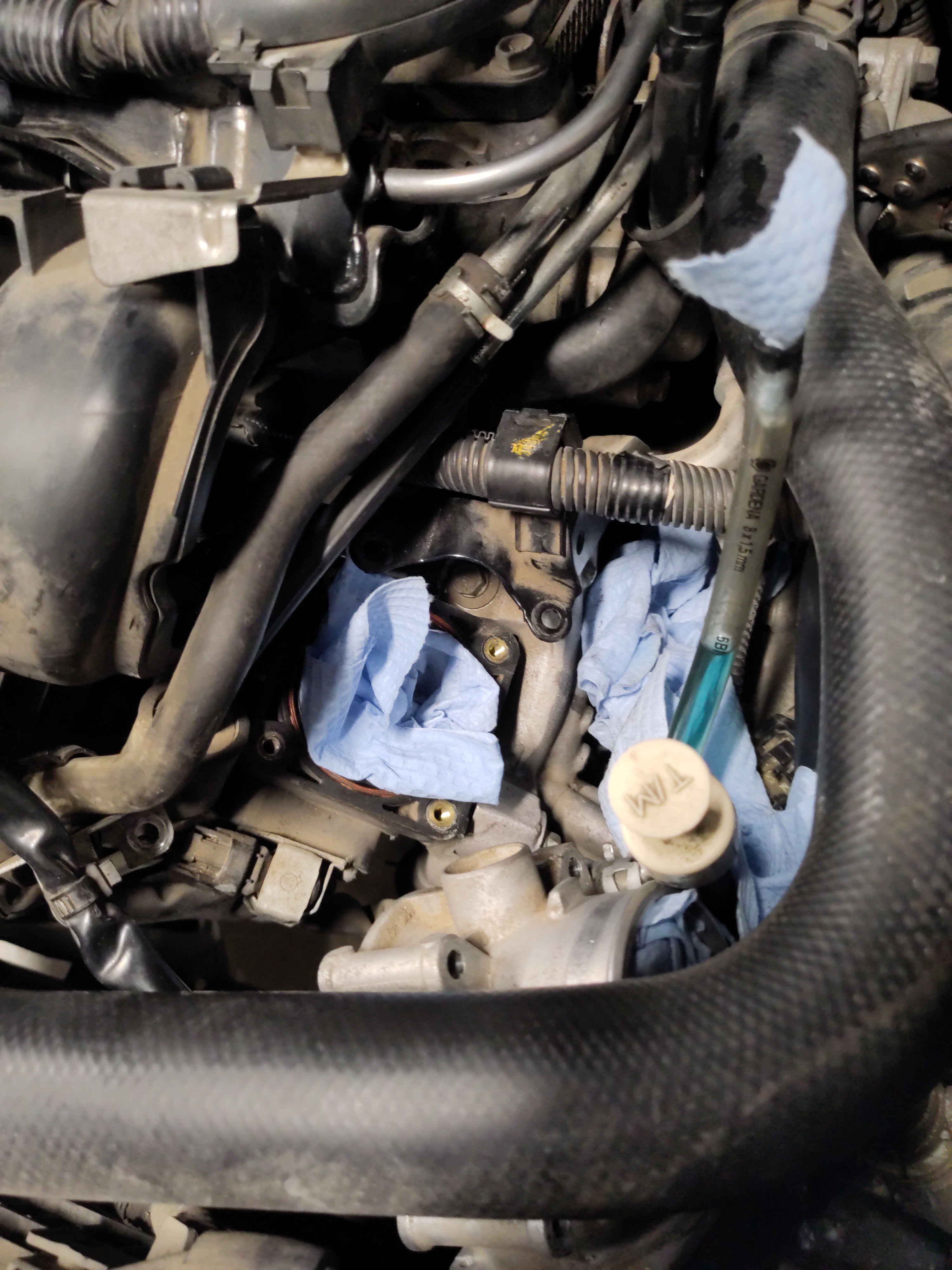
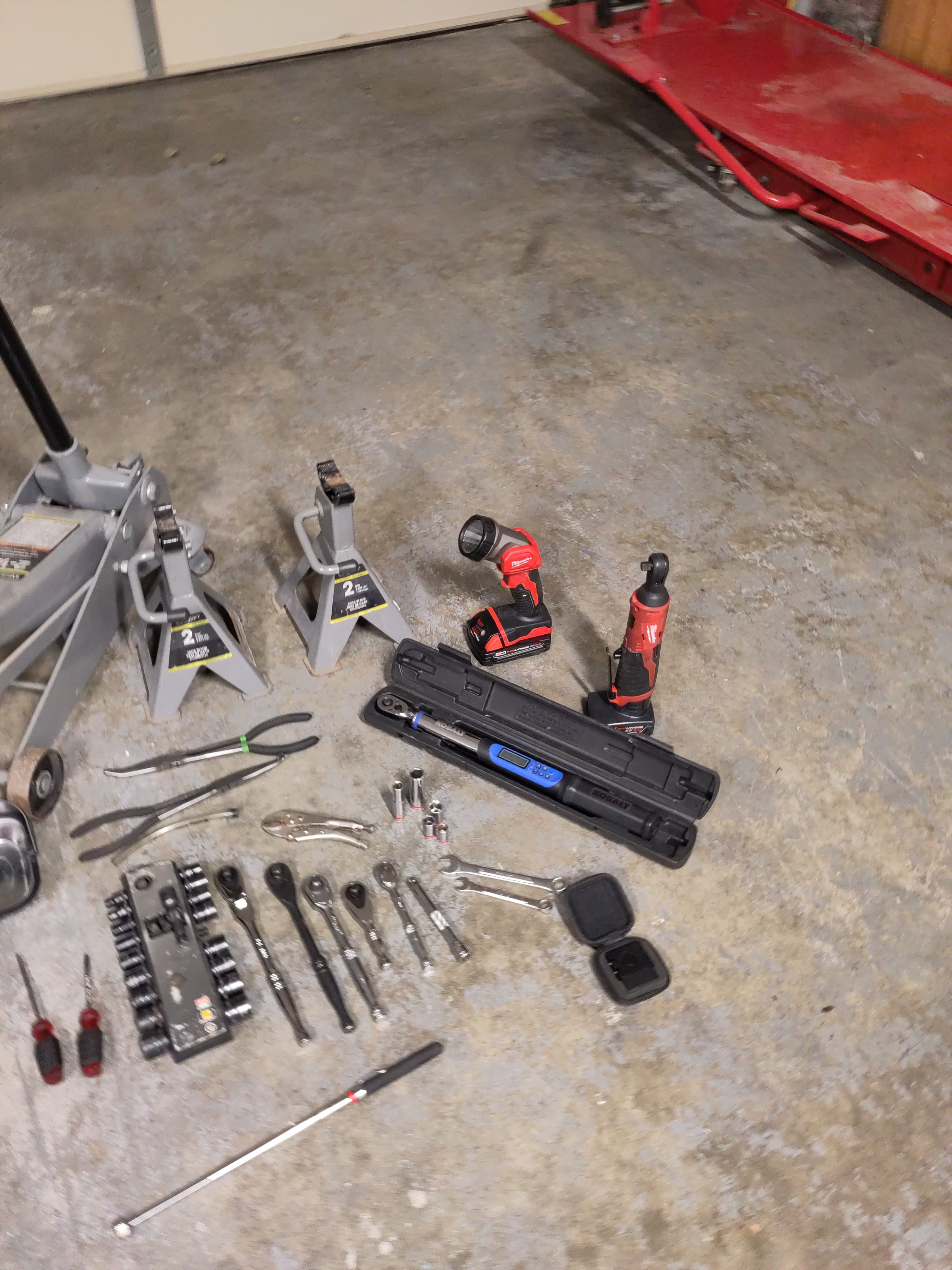
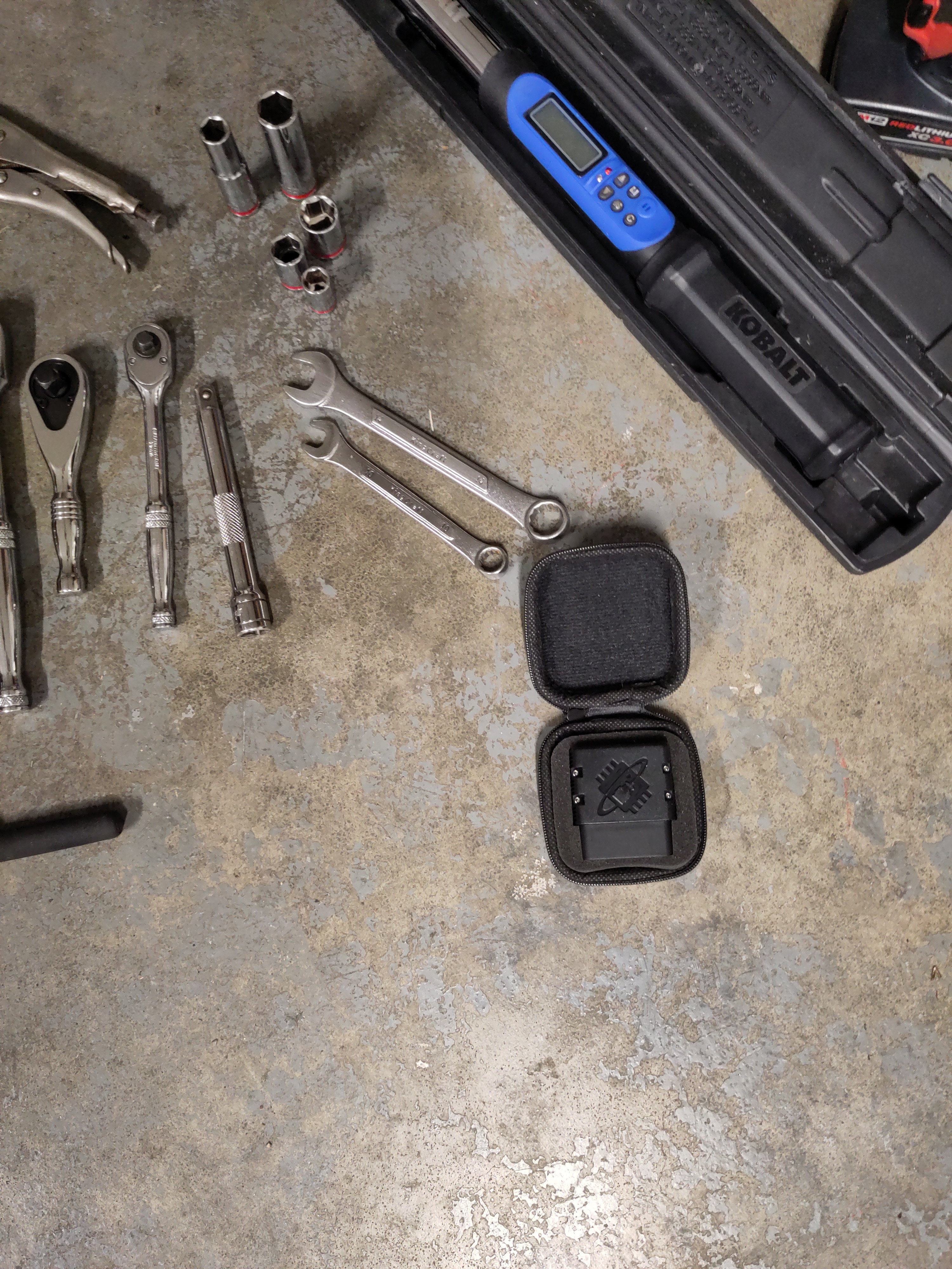
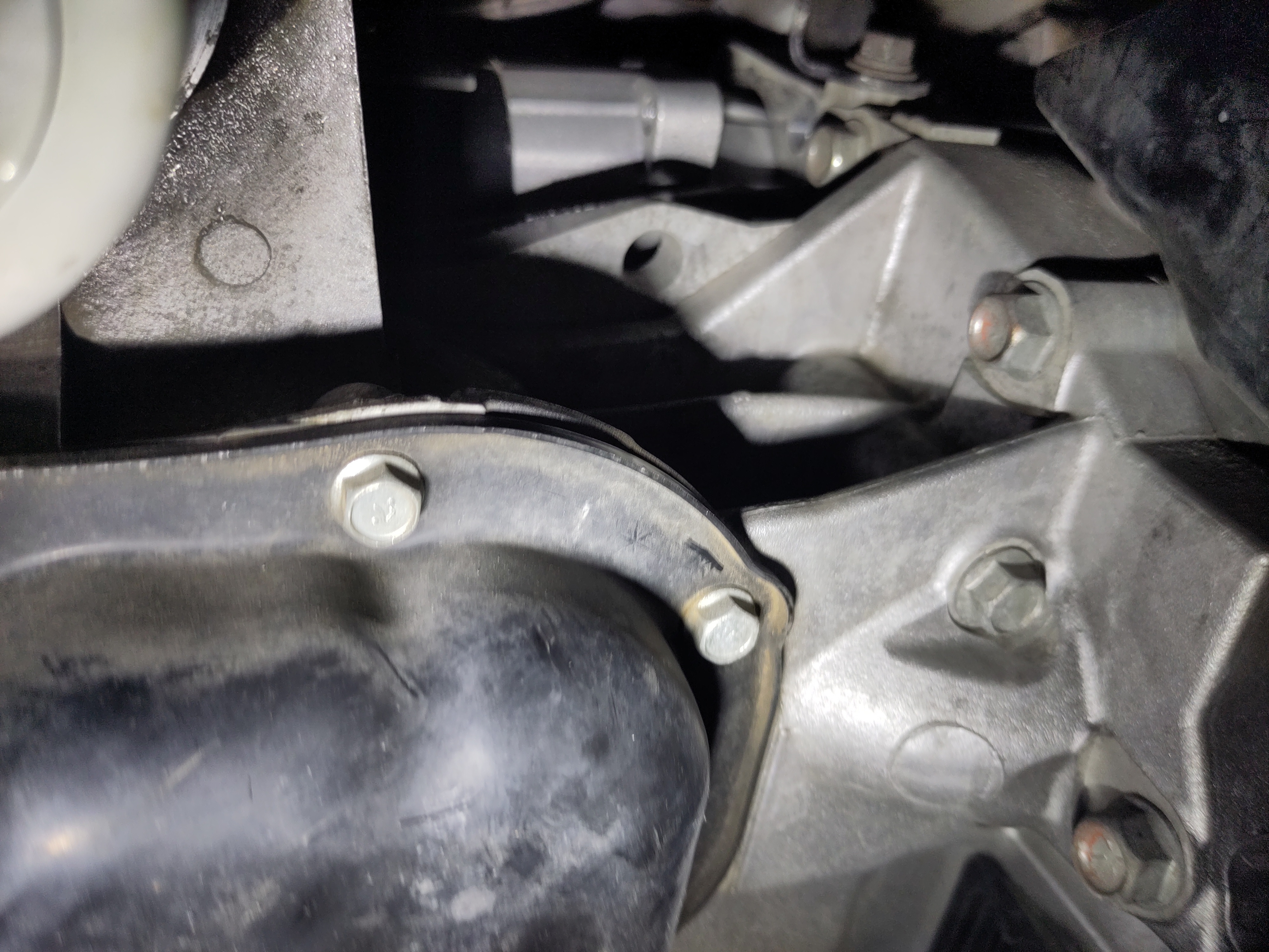
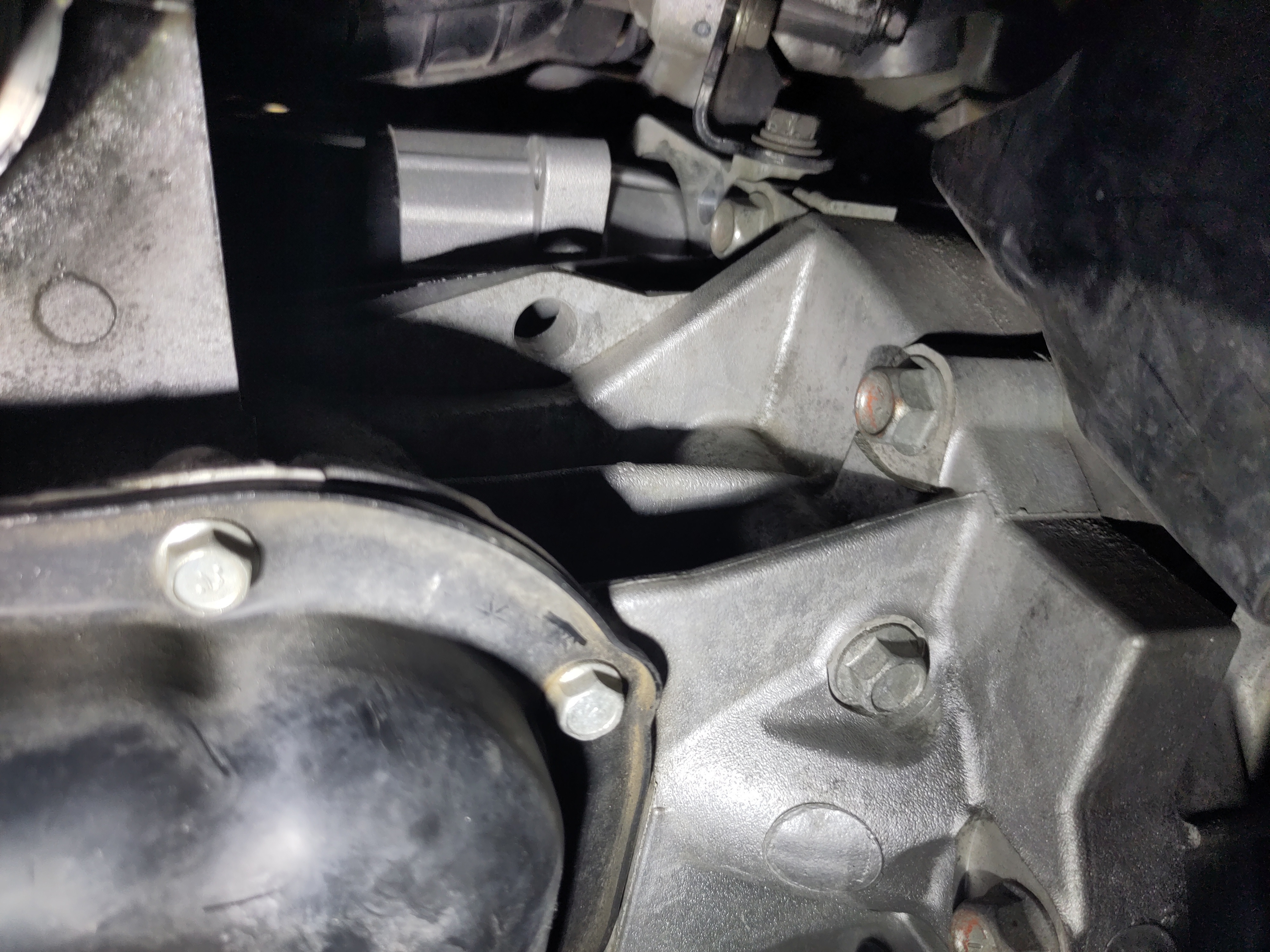
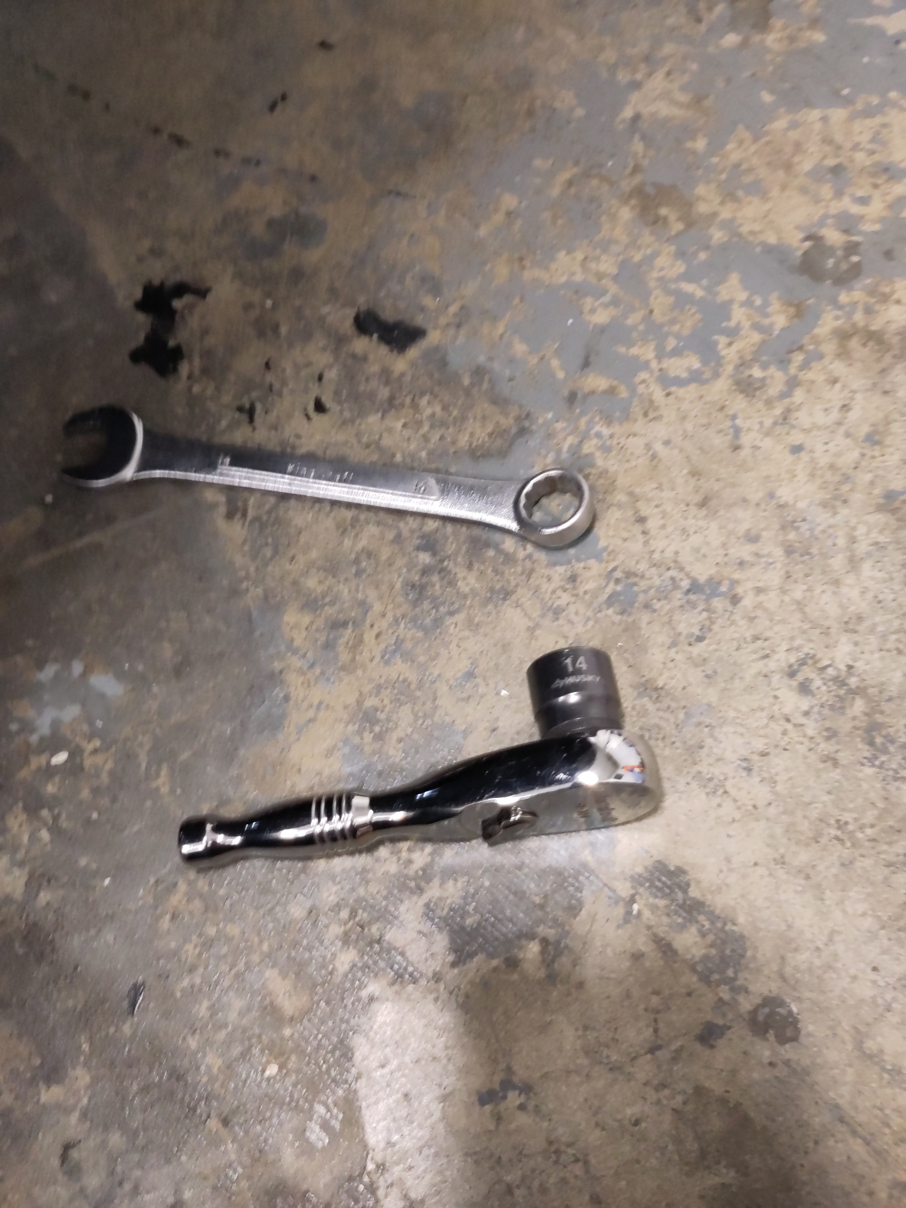
- There are two 14mm bolts securing the starter to the transmission both will be removed using 3/8" drive shallow 14mm 6 point socket and 3/8" drive socket wrench with an adjustable angle will help loosen the top bolt. Out of the two bolts the bottom 14mm bolt will be the most challenging and most time consuming to loosen strictly due to the location and leverage. The range of motion on the top bolt is greater than the bottom bolt and a longer handle socket wrench can be useful while initially breaking the bolt free. For the bottom bolt, I found it useful using different tools to assist in getting the bolt free. I used the short 3/8" drive socket wrench with the 14mm deep socket to initially break the bolt free. Using a normal size 3/8" drive will come with a drawback for limited motion, it was not useful as I initially anticipated. However, using a 14 mm opened wrench and 12 point closed end helped in further loosening the bolt. For visibility the use a flashlight and can get dark and difficult to see the bolt. IMPORTANT! Recommendation would be to keep the the bottom 14mm bolt threaded into the starter just to create some with the starter for when disconnecting the electrical connections to the starter. The top bolt once removed should be stored in the magnetic pan for safe keeping.
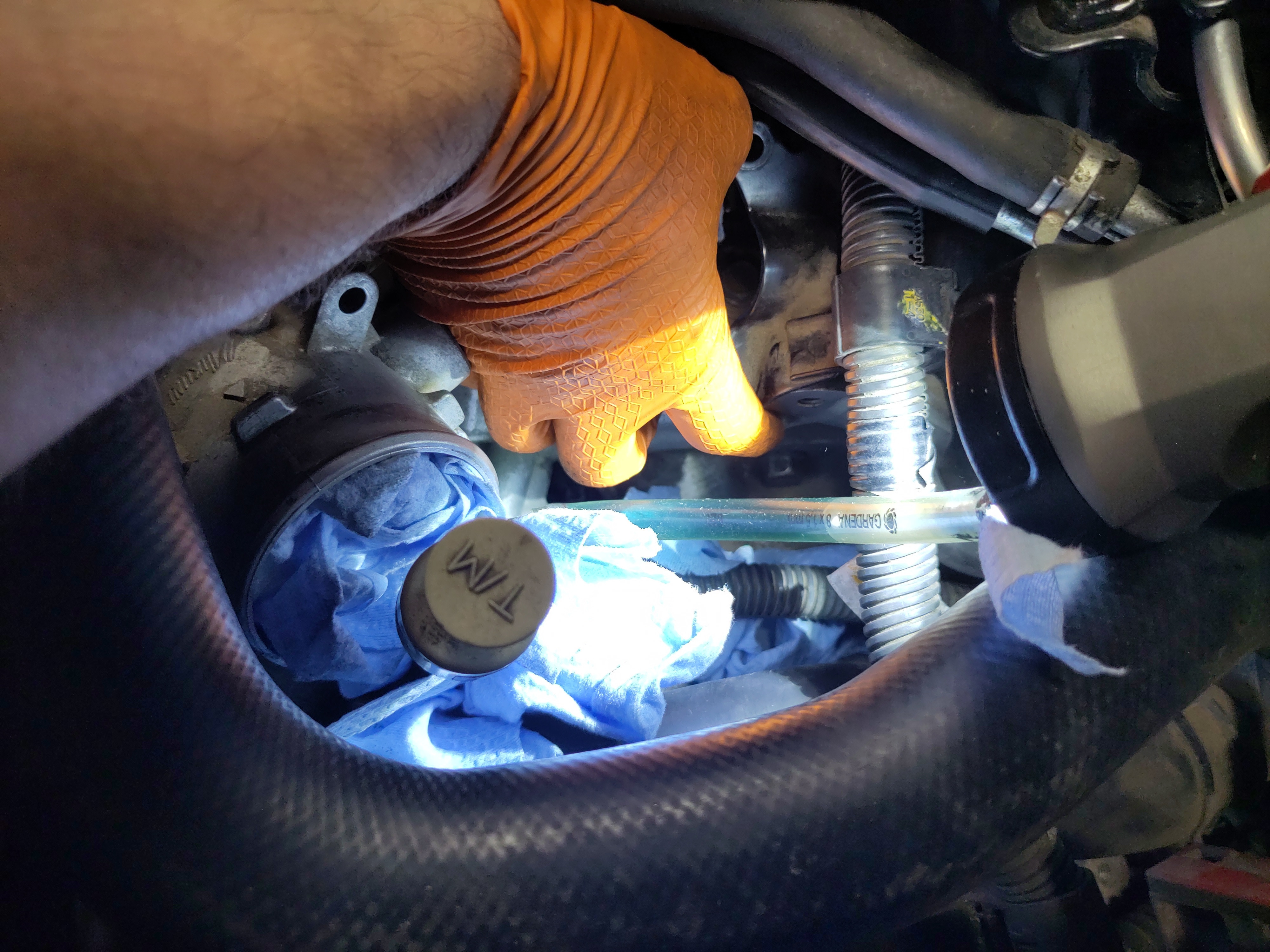
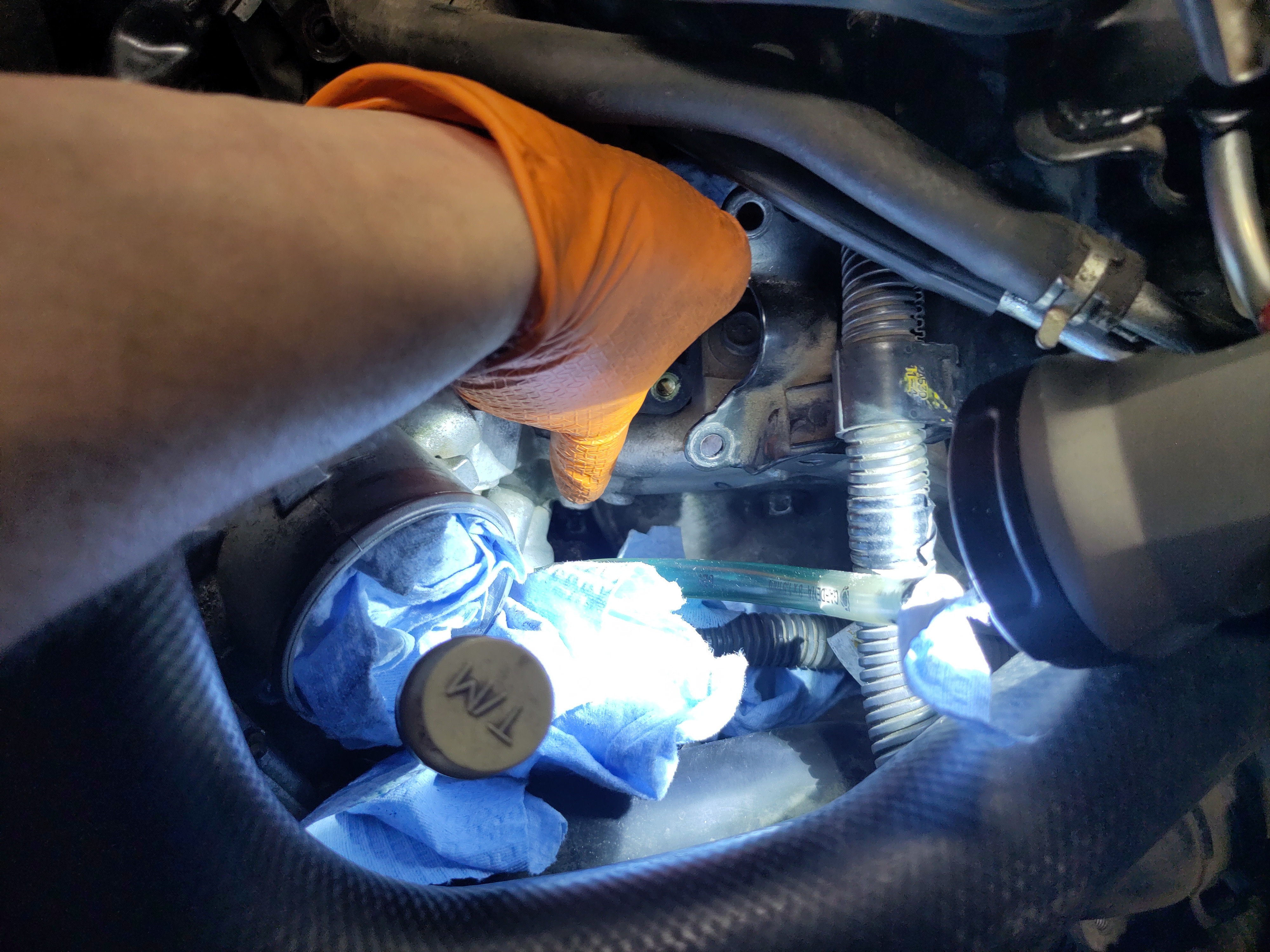
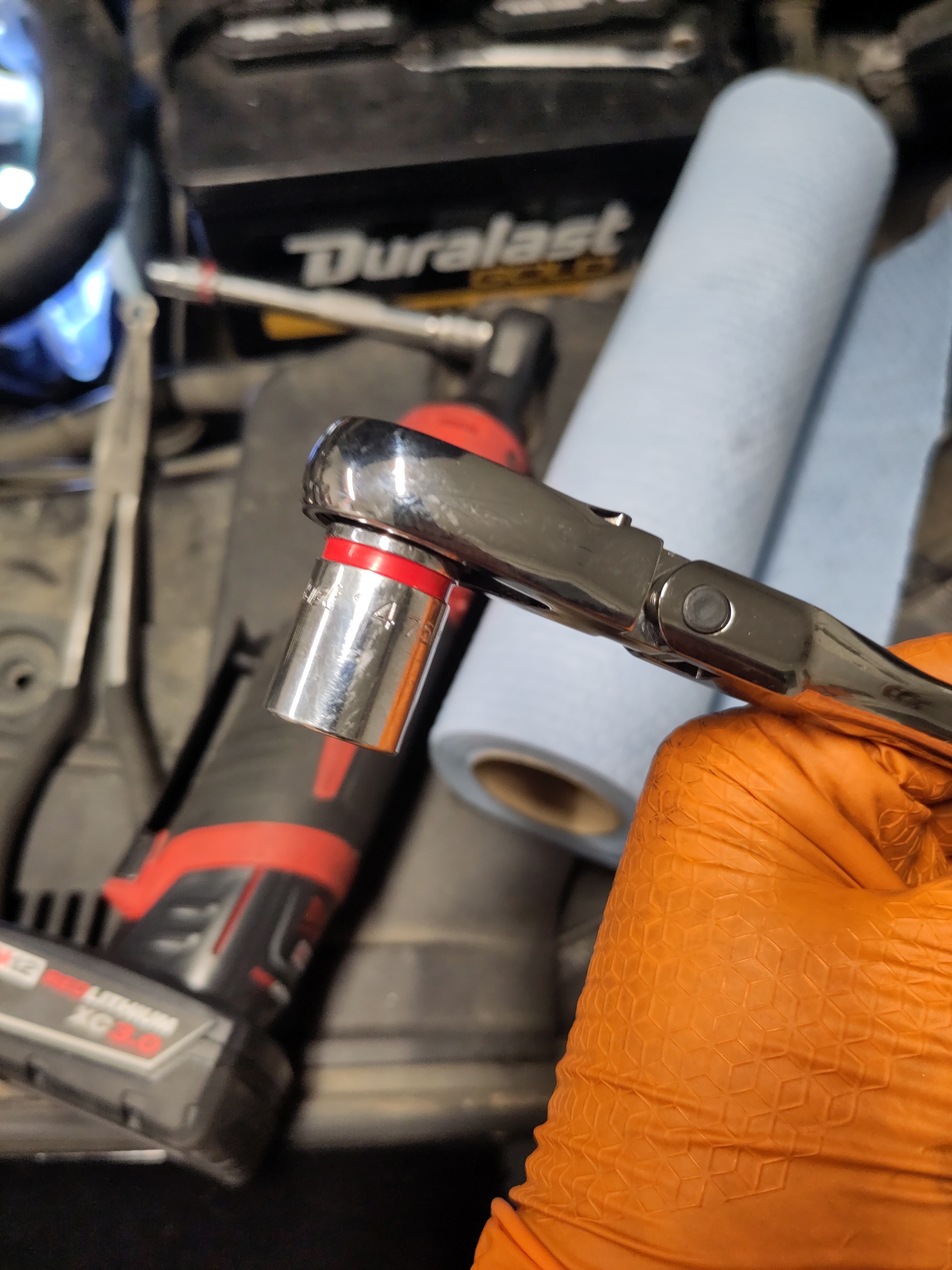
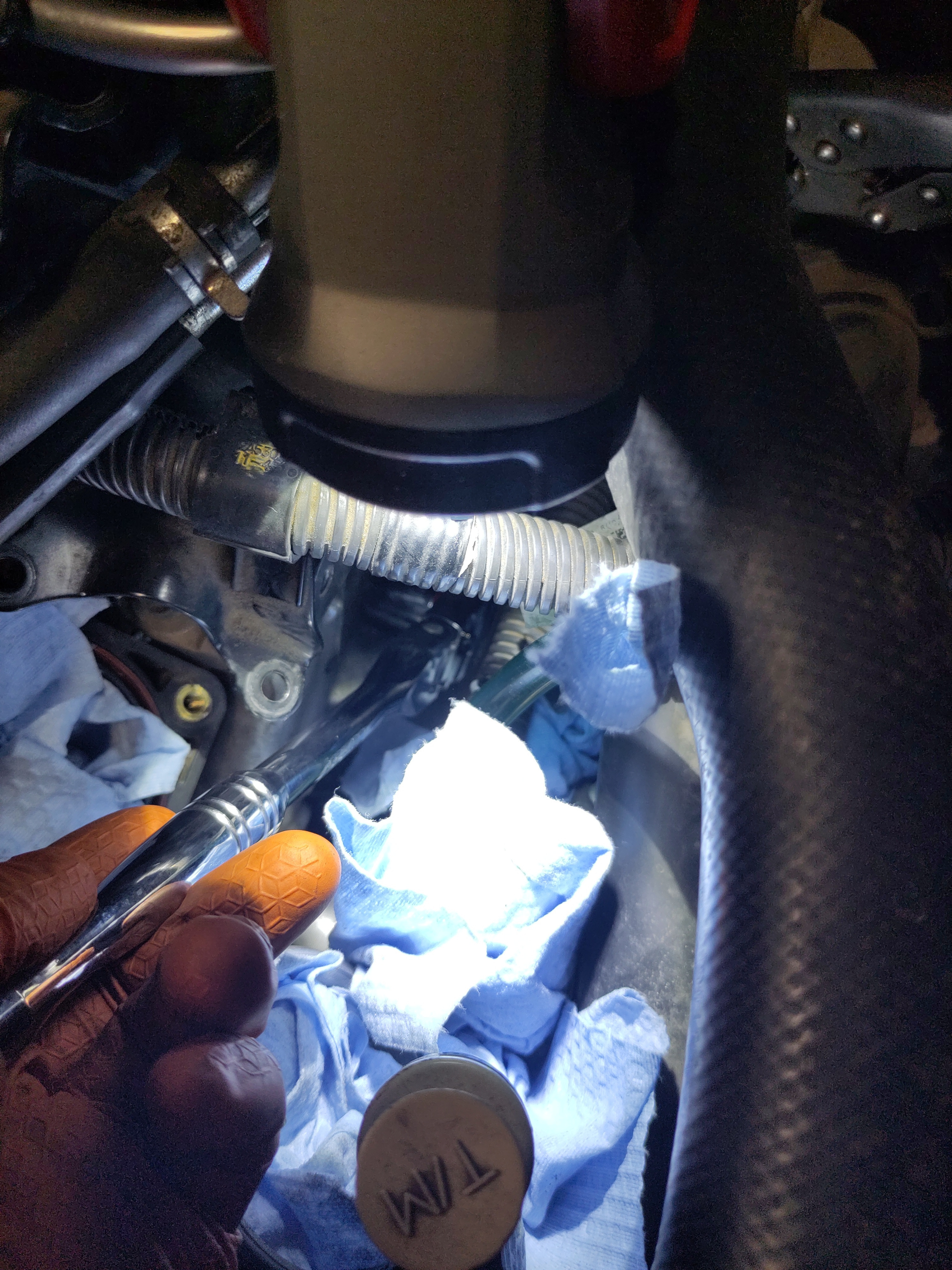
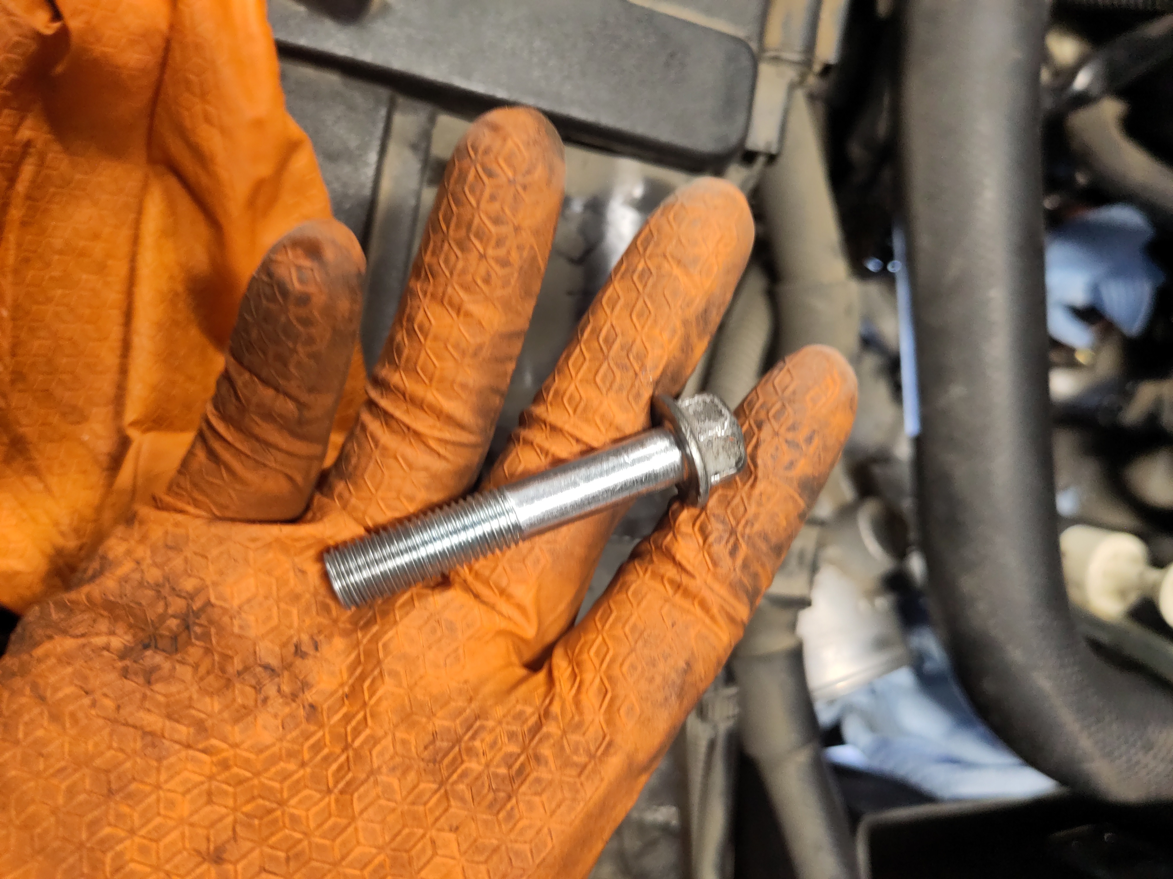
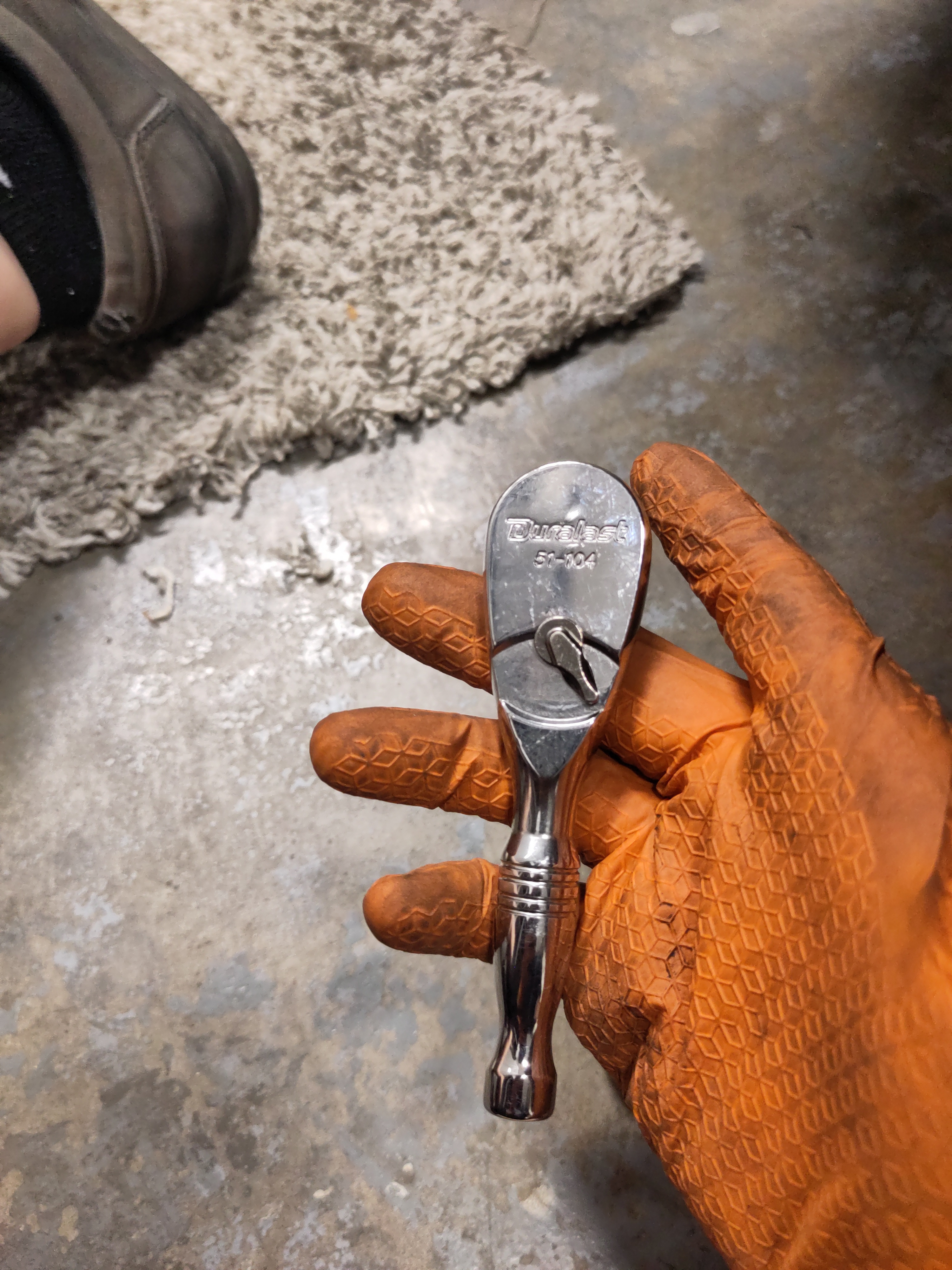
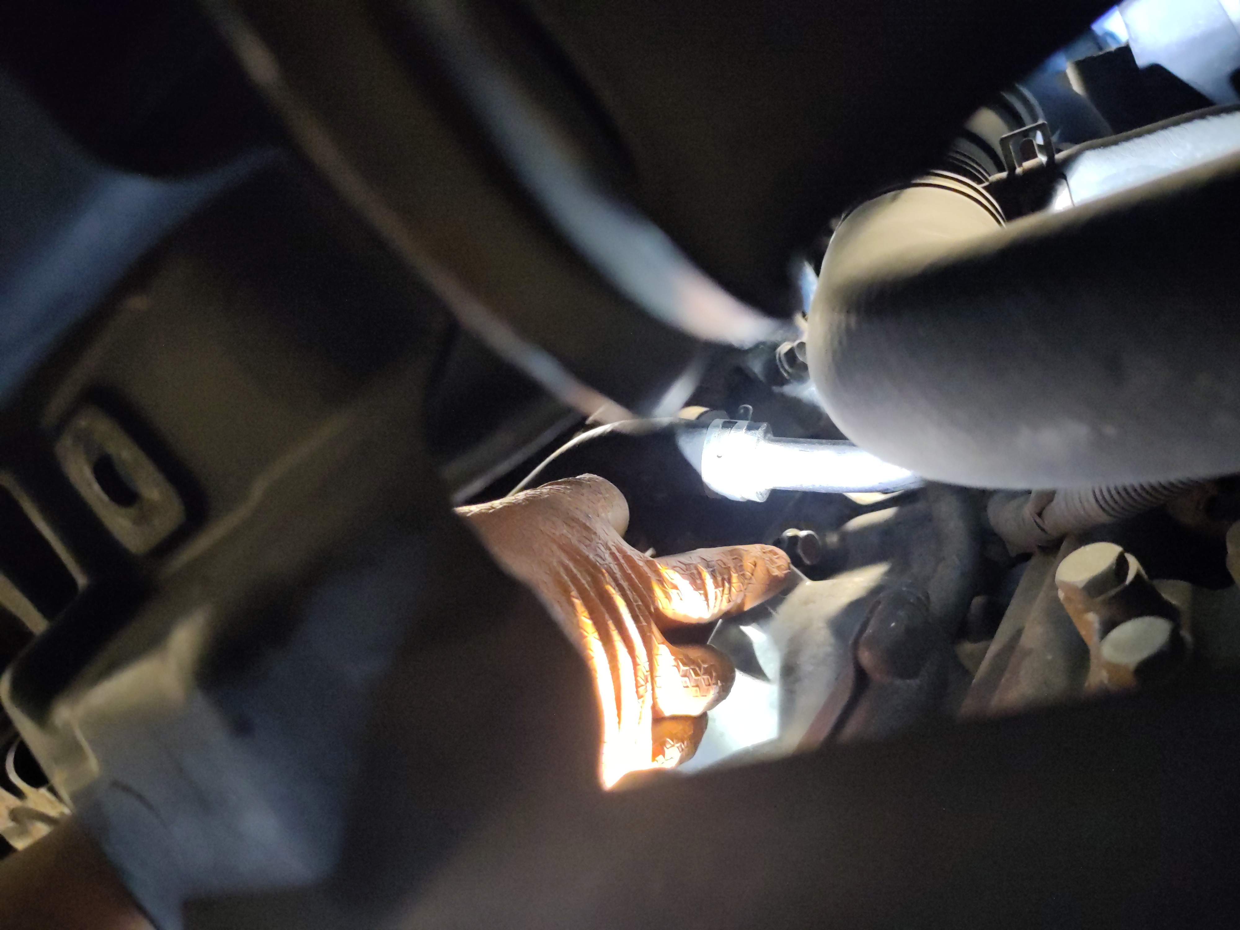
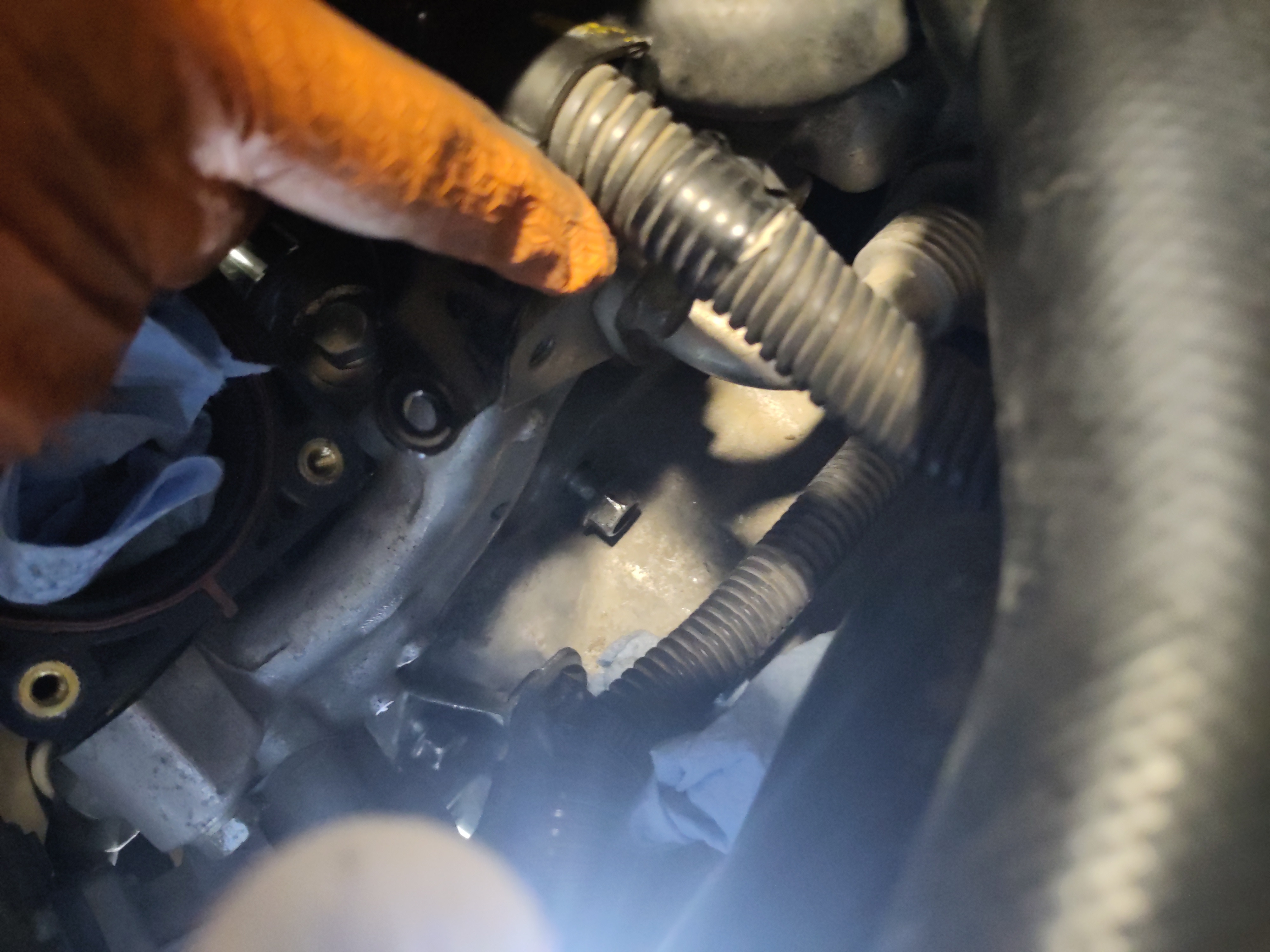
- The starter is seated underneath the exhaust manifold which is where the electrical connections are located. It can be challenging in getting to them, but it was permissible by sticking left arm around the refrigeration hose and in between the manifold to create leverage and ease. If it difficult, try removing some hoses or components are hindering the accessibility of loosening the electrical connections. See photos below for a better understanding. There is a four pin electrical connection that will be need to be undone. Using your fingers at the proper angling you can disconnect the electrical connection by
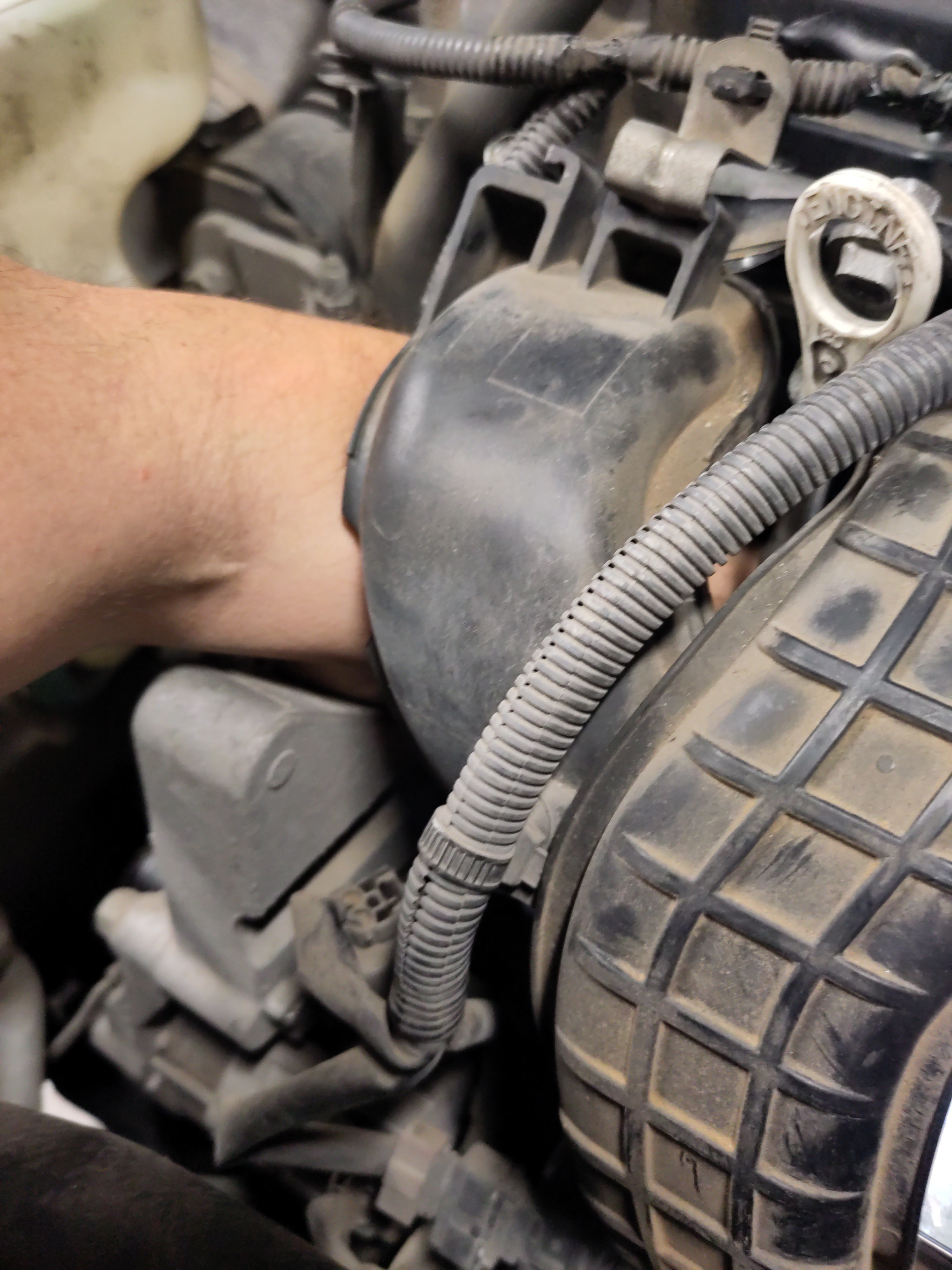
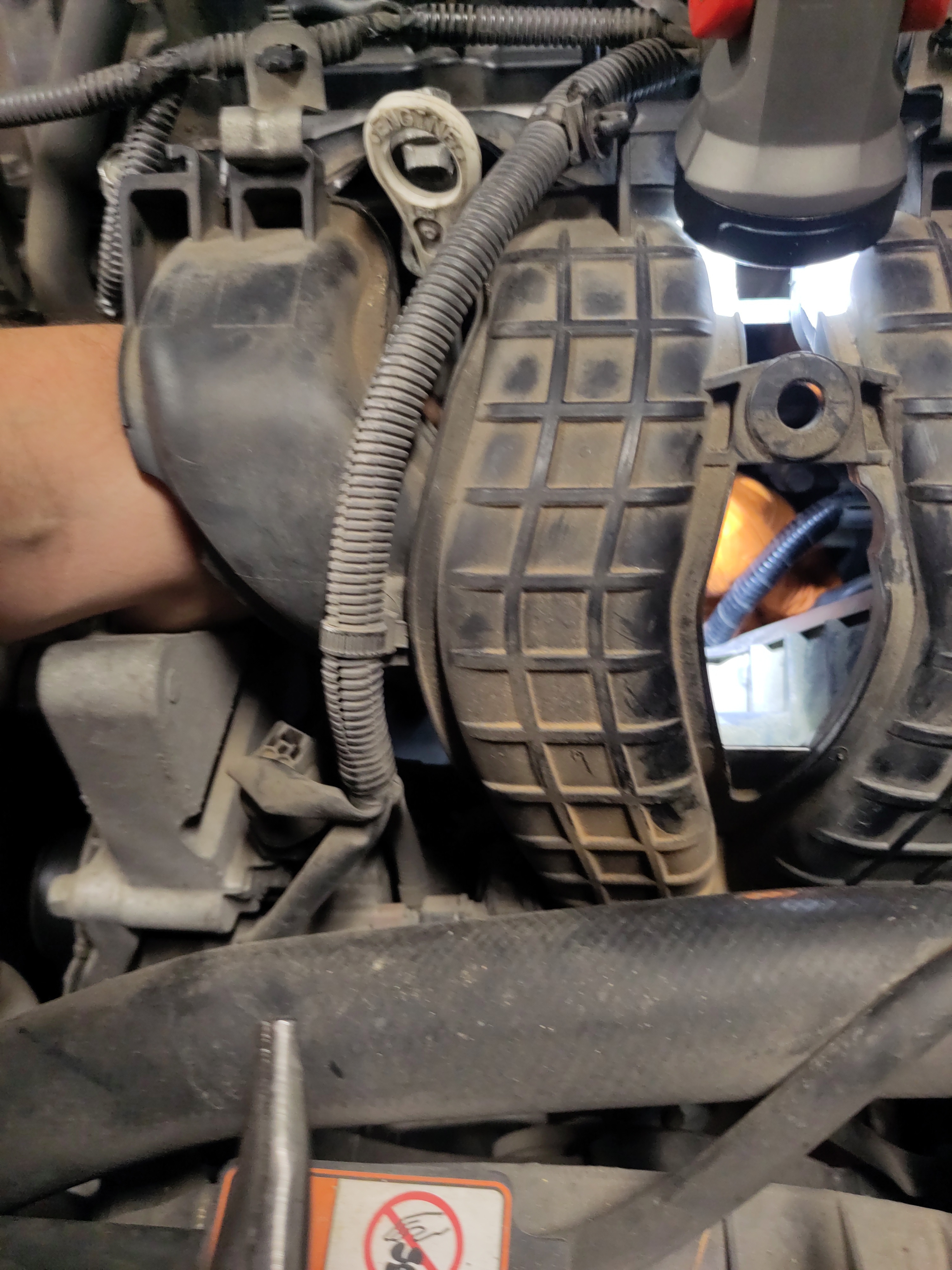
- There is a four pin electrical connection that will be need to be undone. Using your fingers at the proper angling you can disconnect the electrical connection by pressing it. If necessary use the tip of nose pliers to press into the pin and pull the wiring harness simultaneously.
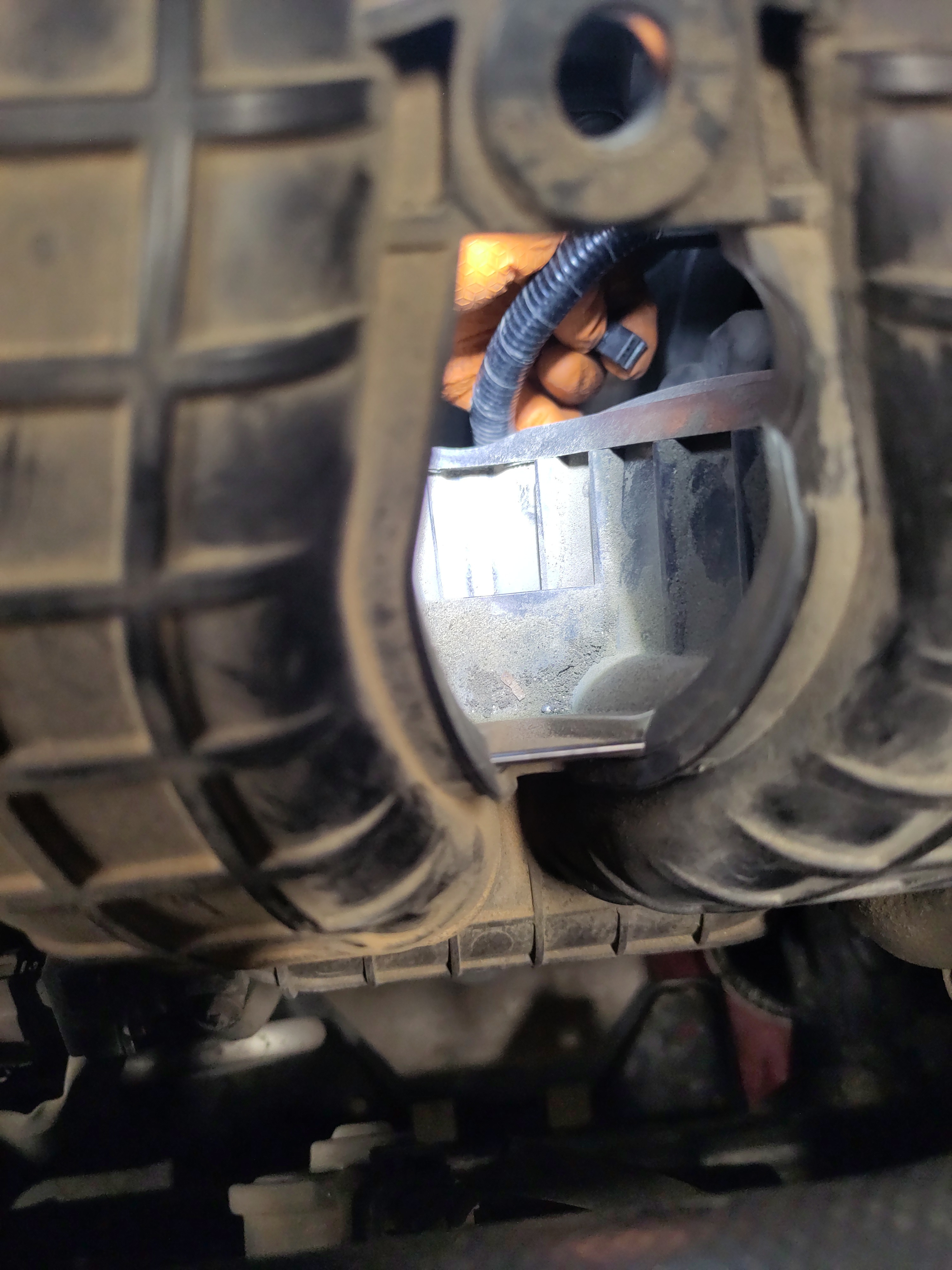
- There is a rubber boot is concealing the positive terminal of the starter and there is a 12mm nut securing it. Using a 3/8" drive 12 mm 12 point shallow socket with a 3/8" drive socket wrench with an extension, it will be rather easy to undo the nut. If the nut falls into the cracks of the engine then use a magnetic pickup tool to retrieve the nut. Put the nut into the magnetic hardware pan for safe keeping.
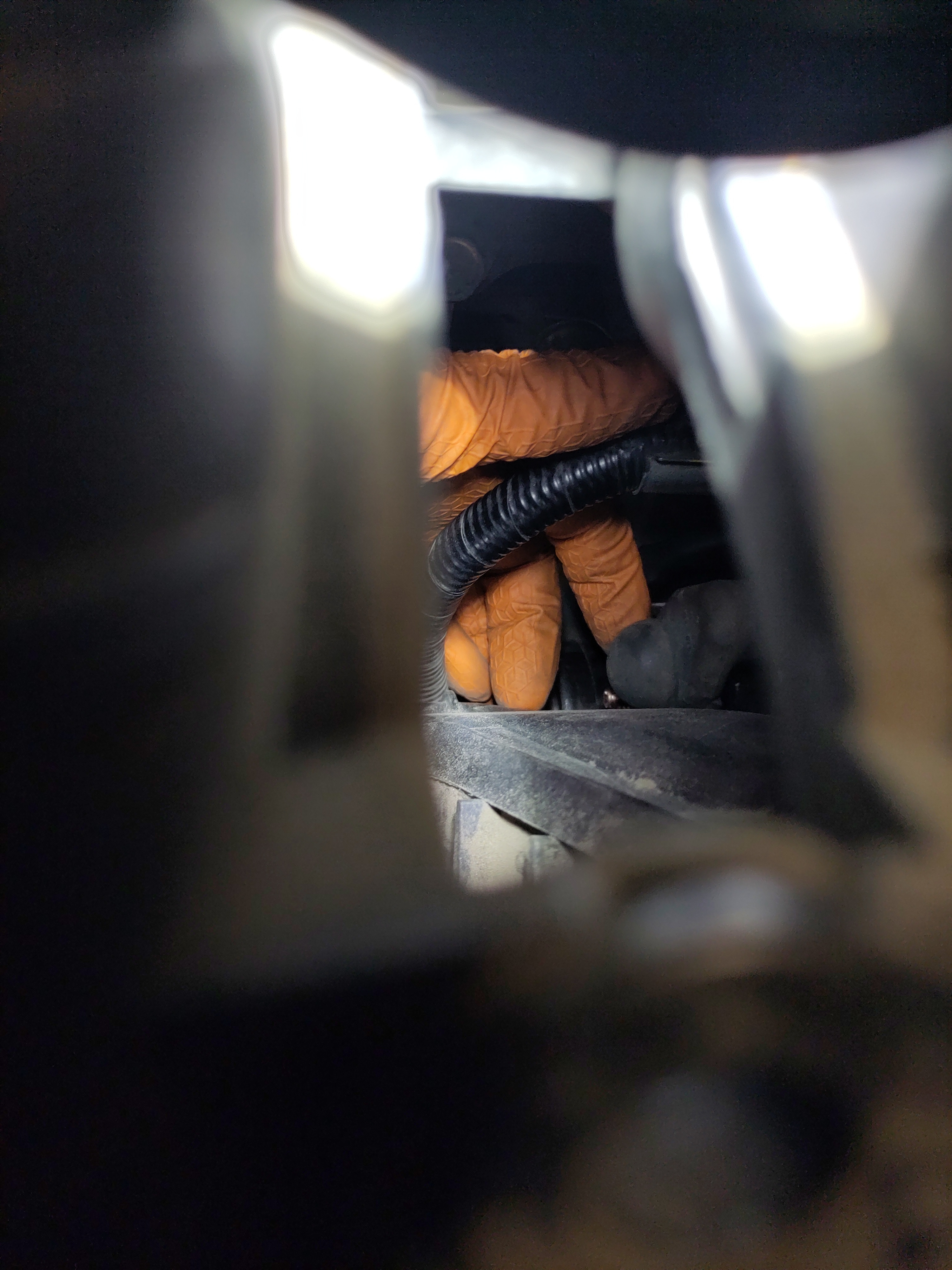
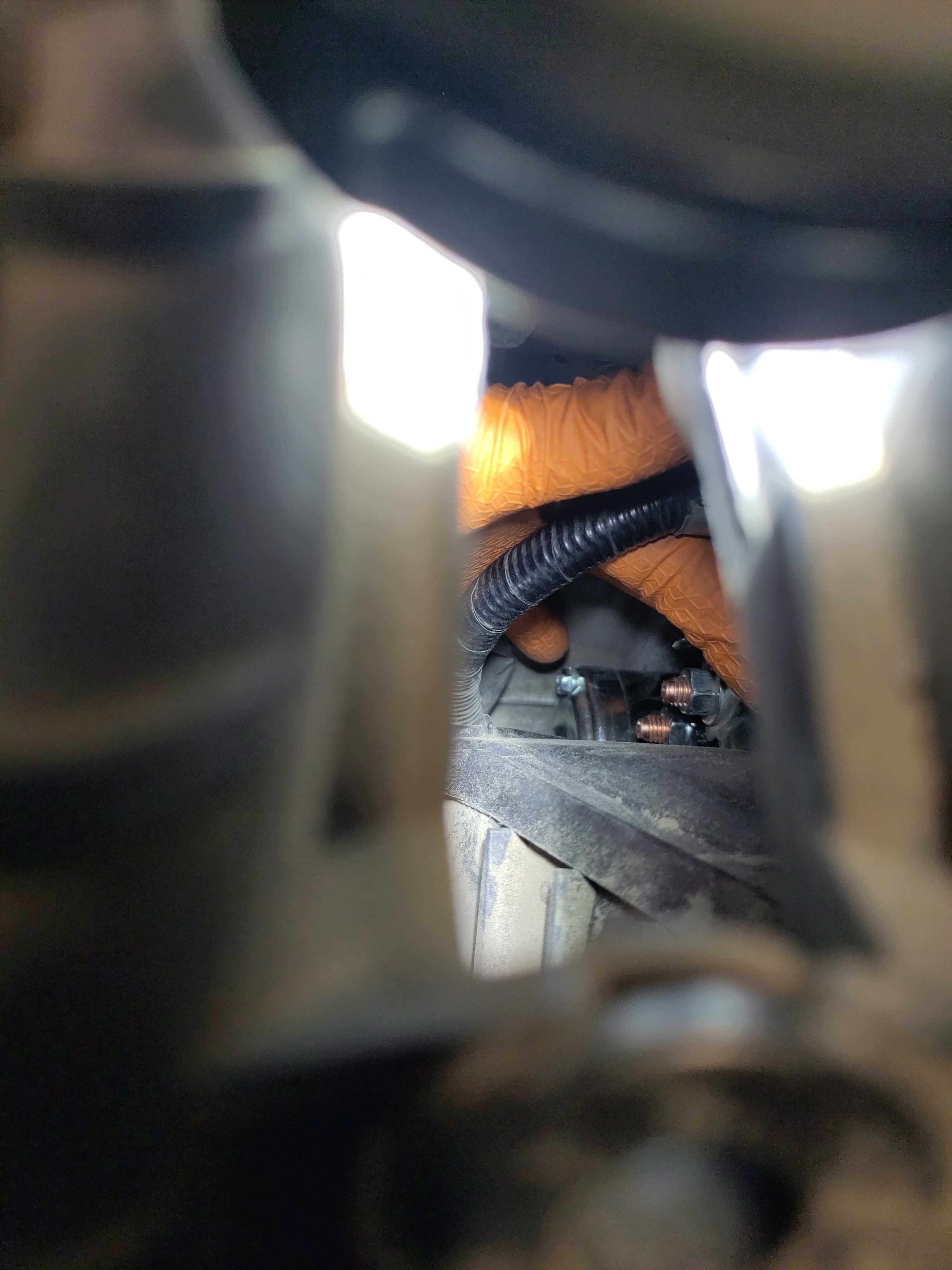
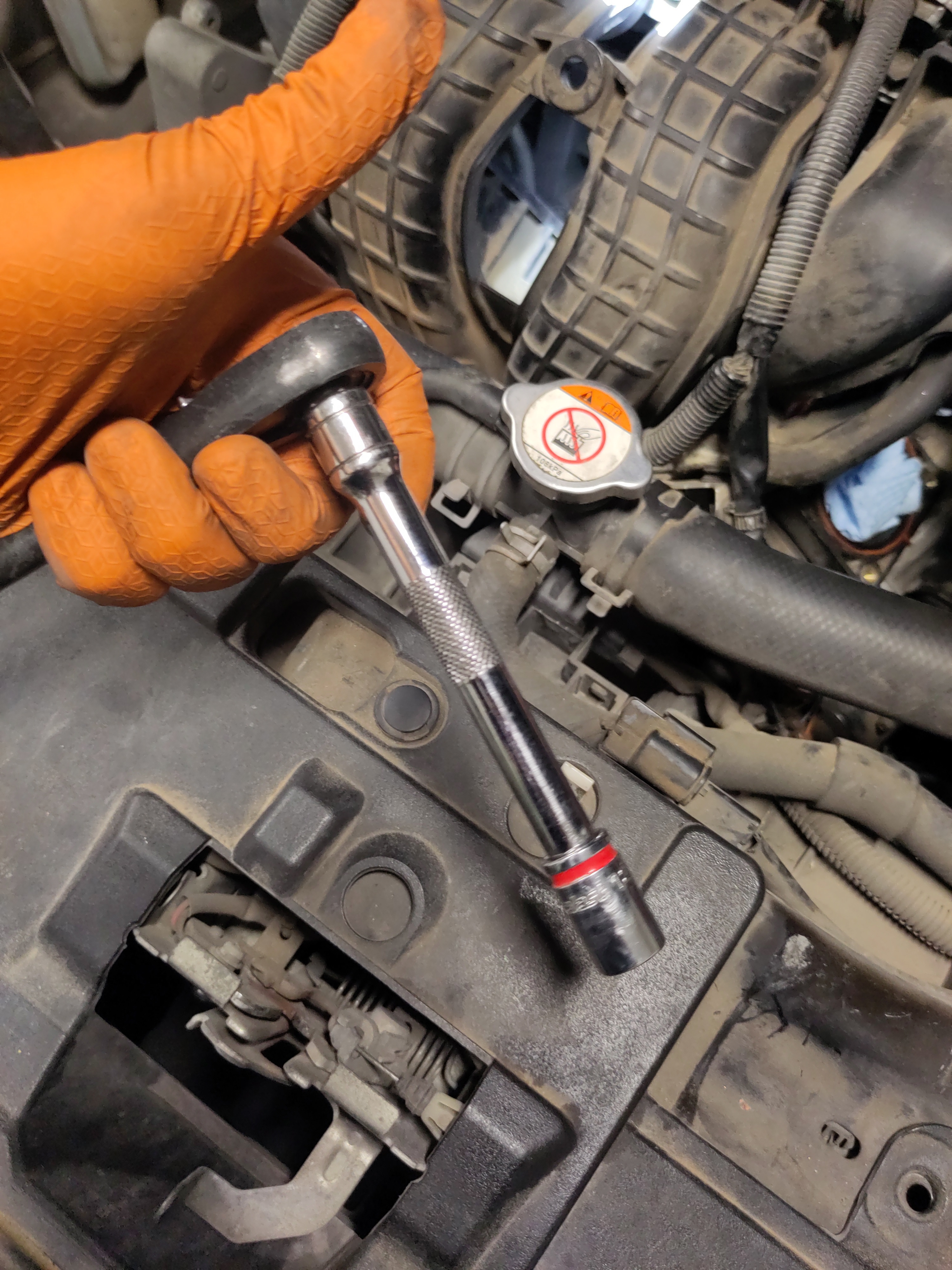
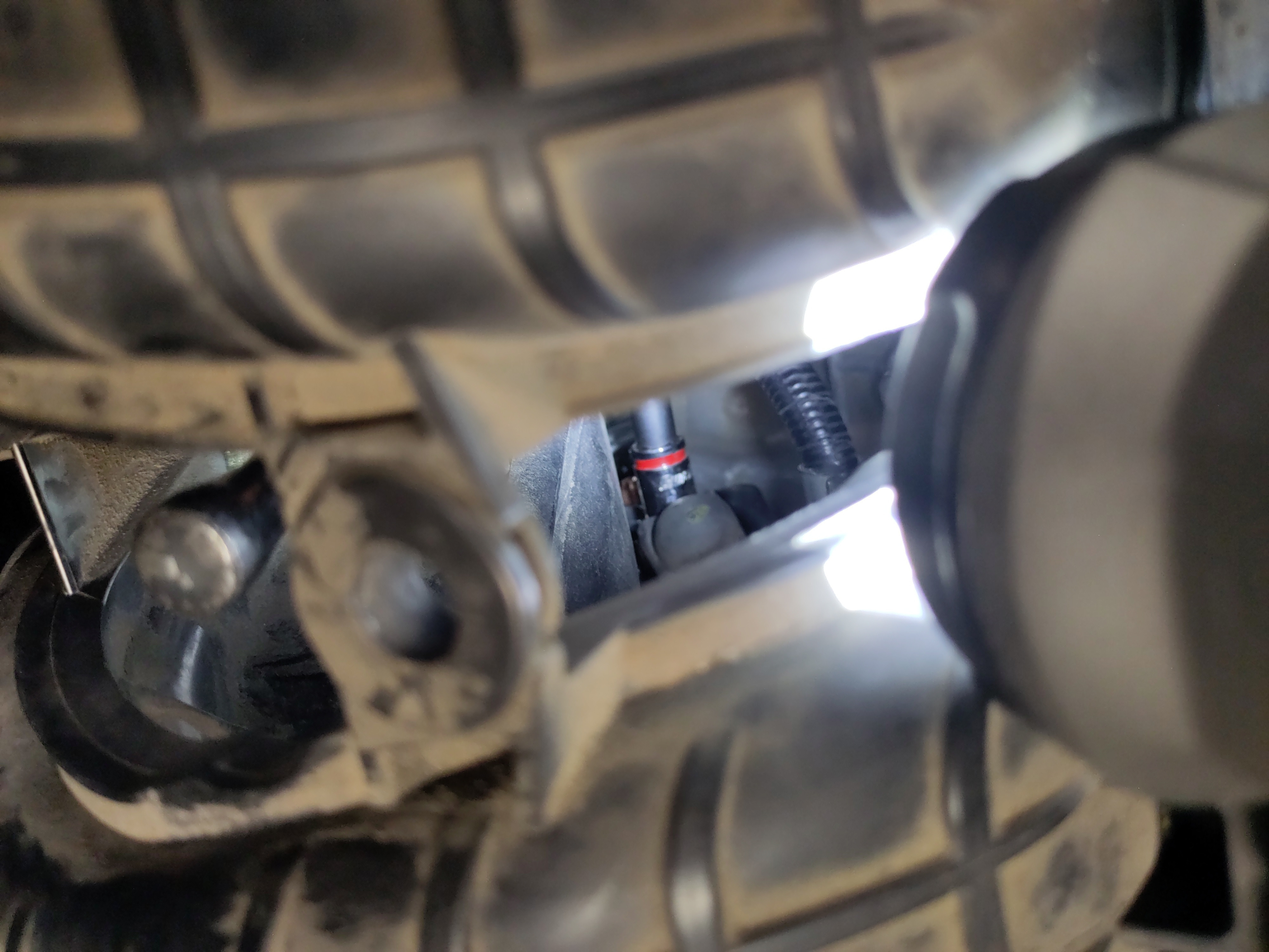
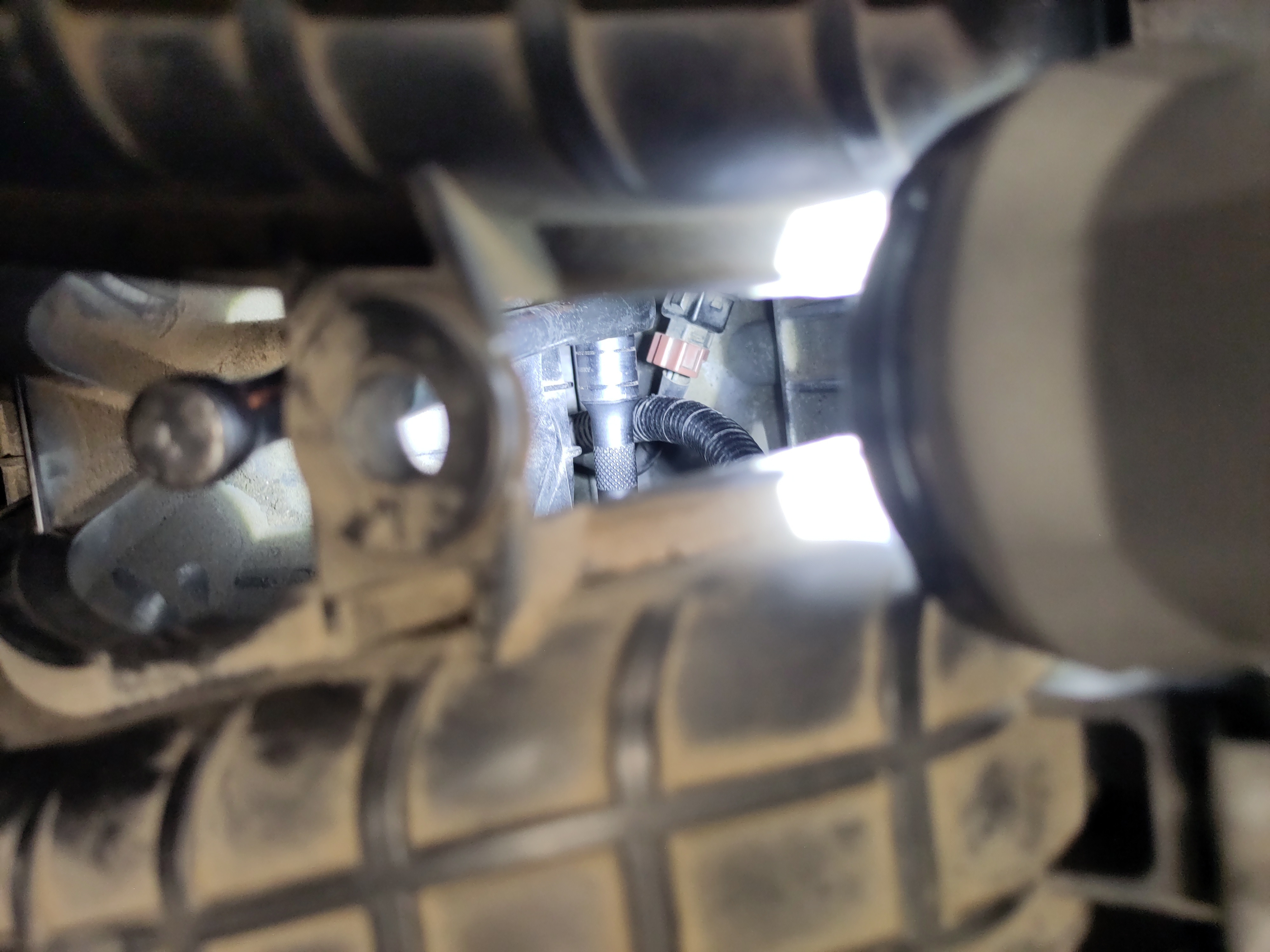
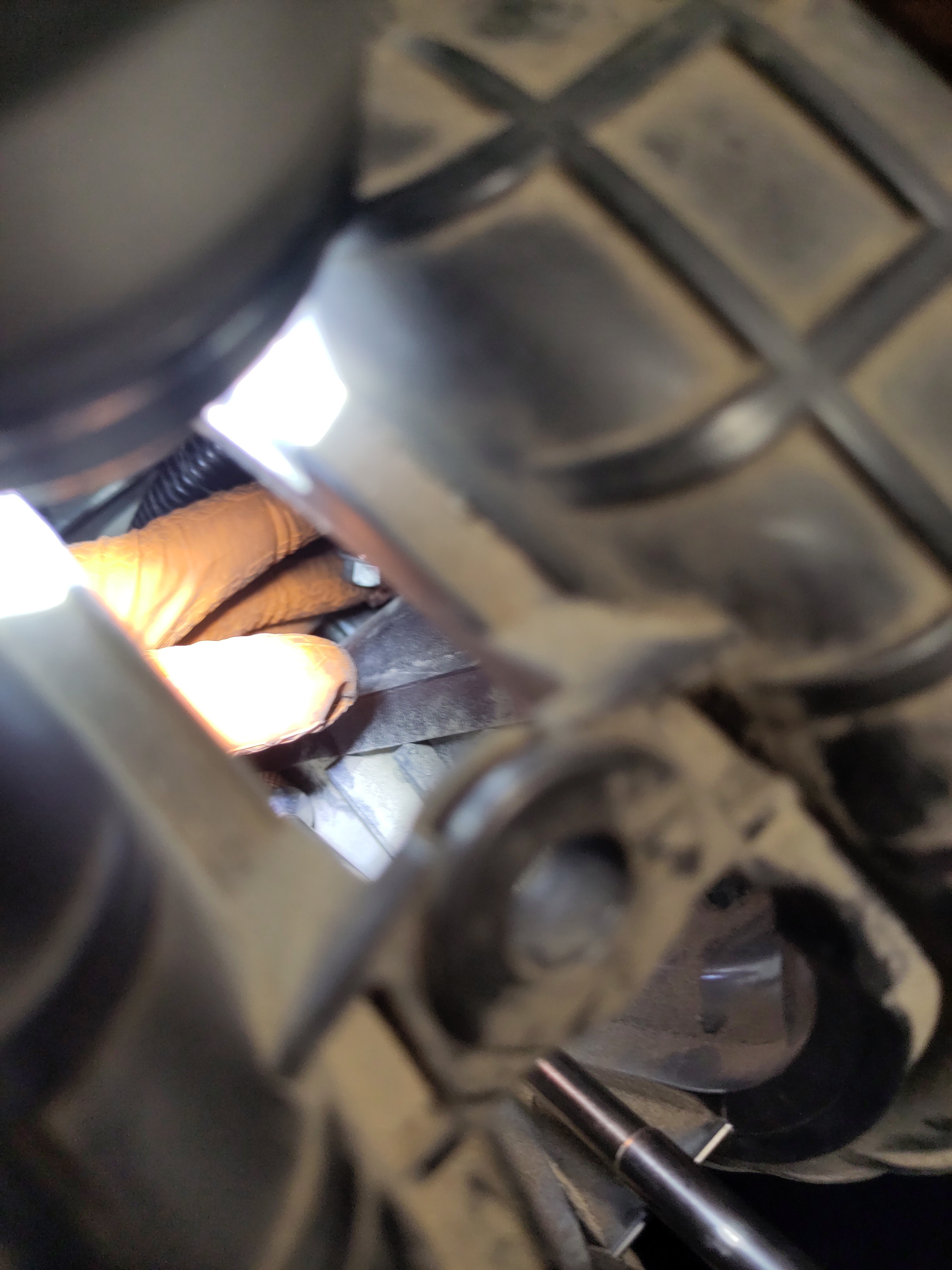
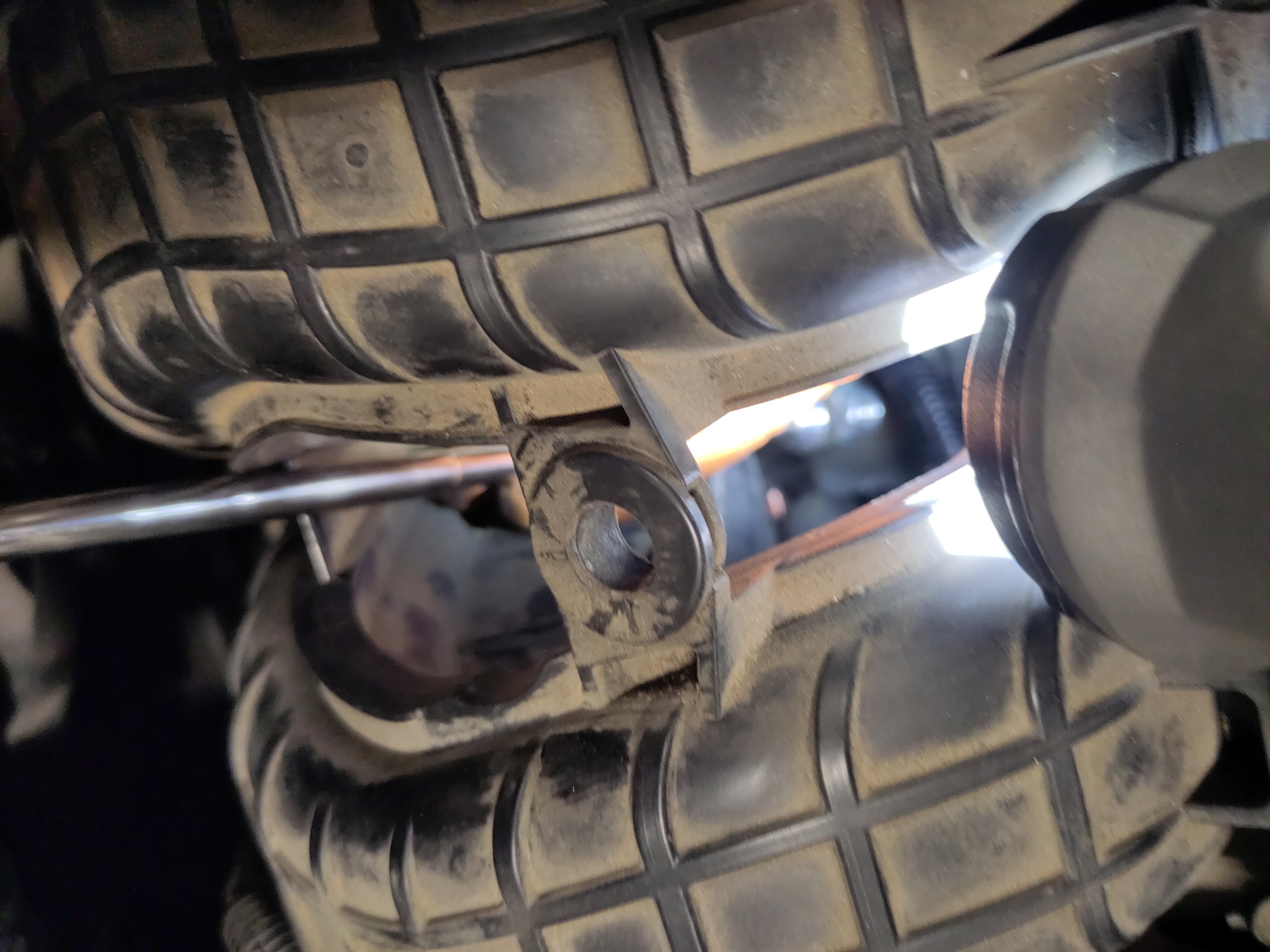
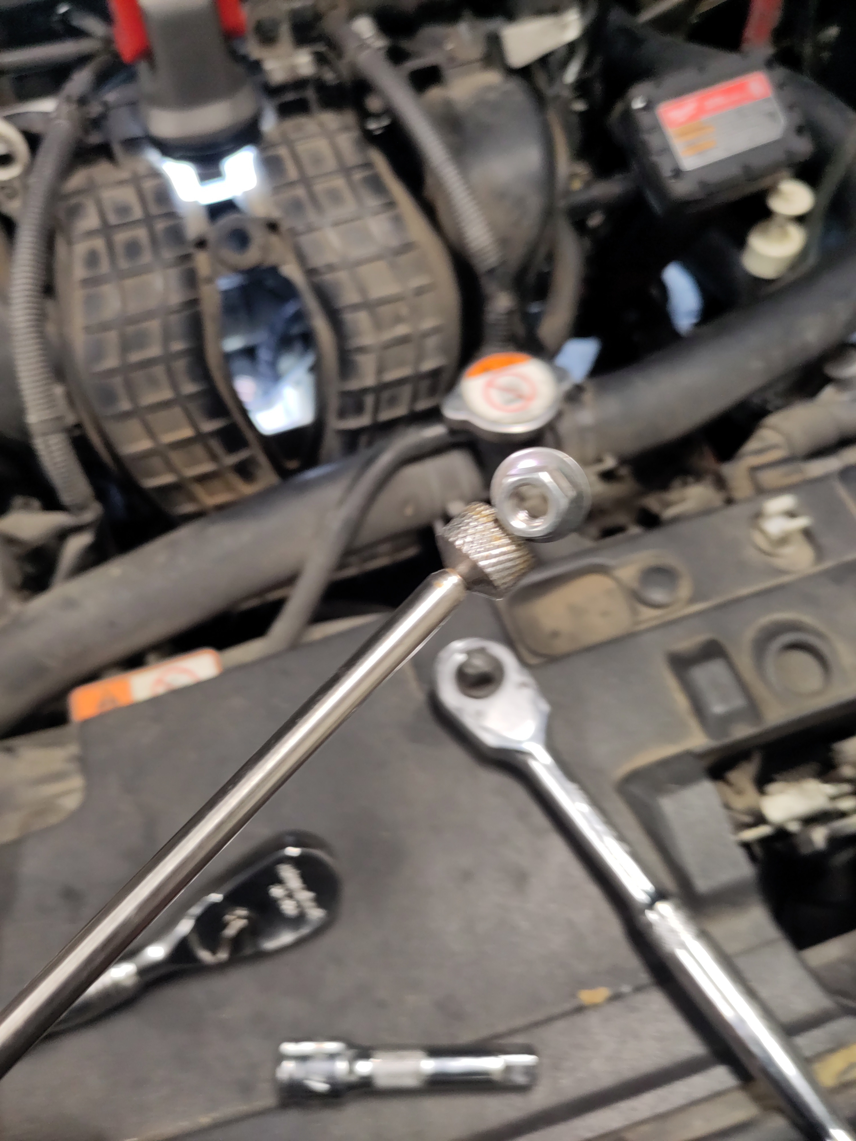
- Now go under the vehicle using the 14mm 12 point shallow socket and a short handle 3/8" drive to finish removing the starter bolt. Place the bolt with the other starter bolt in magnetic pan for safe keeping.
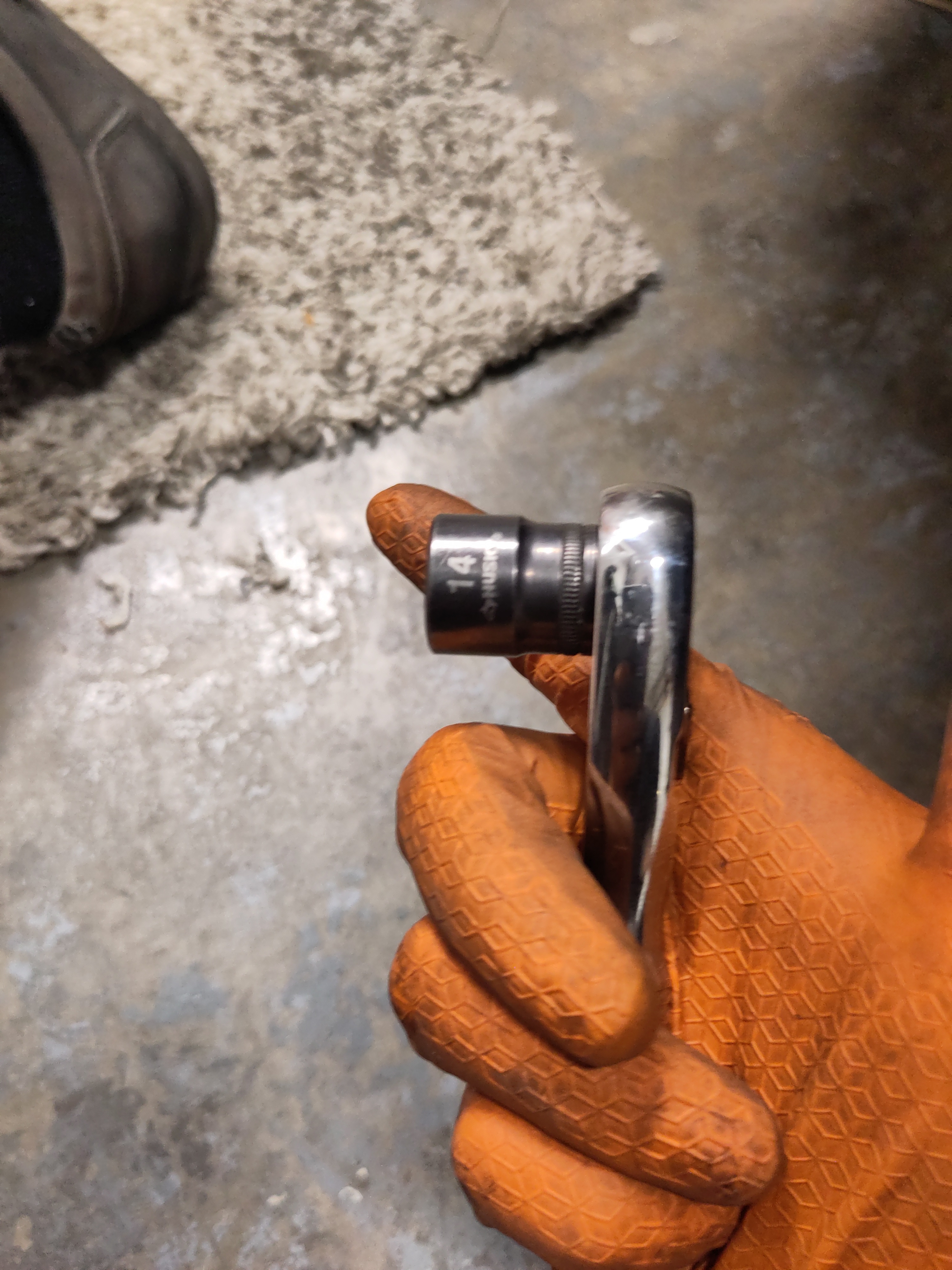
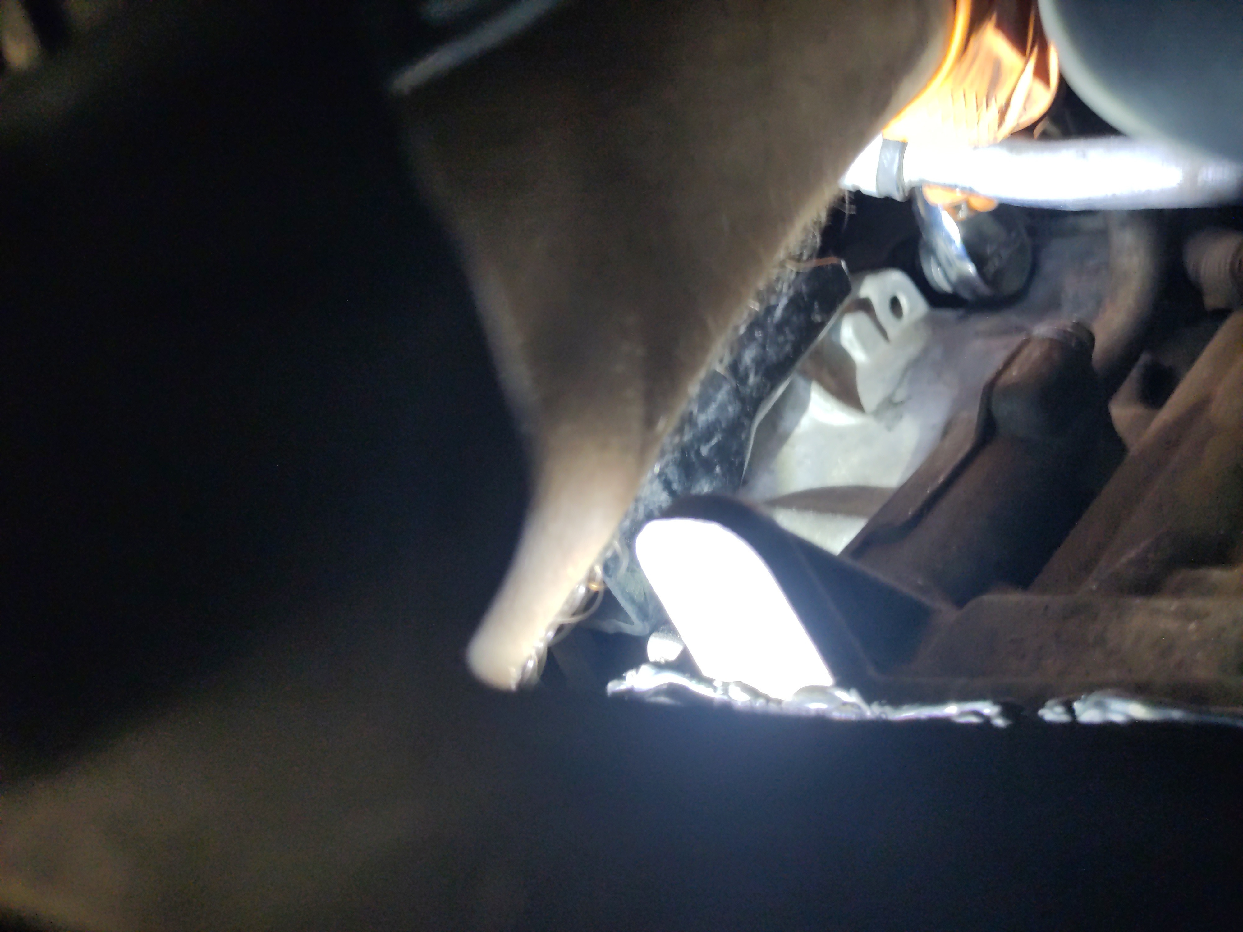
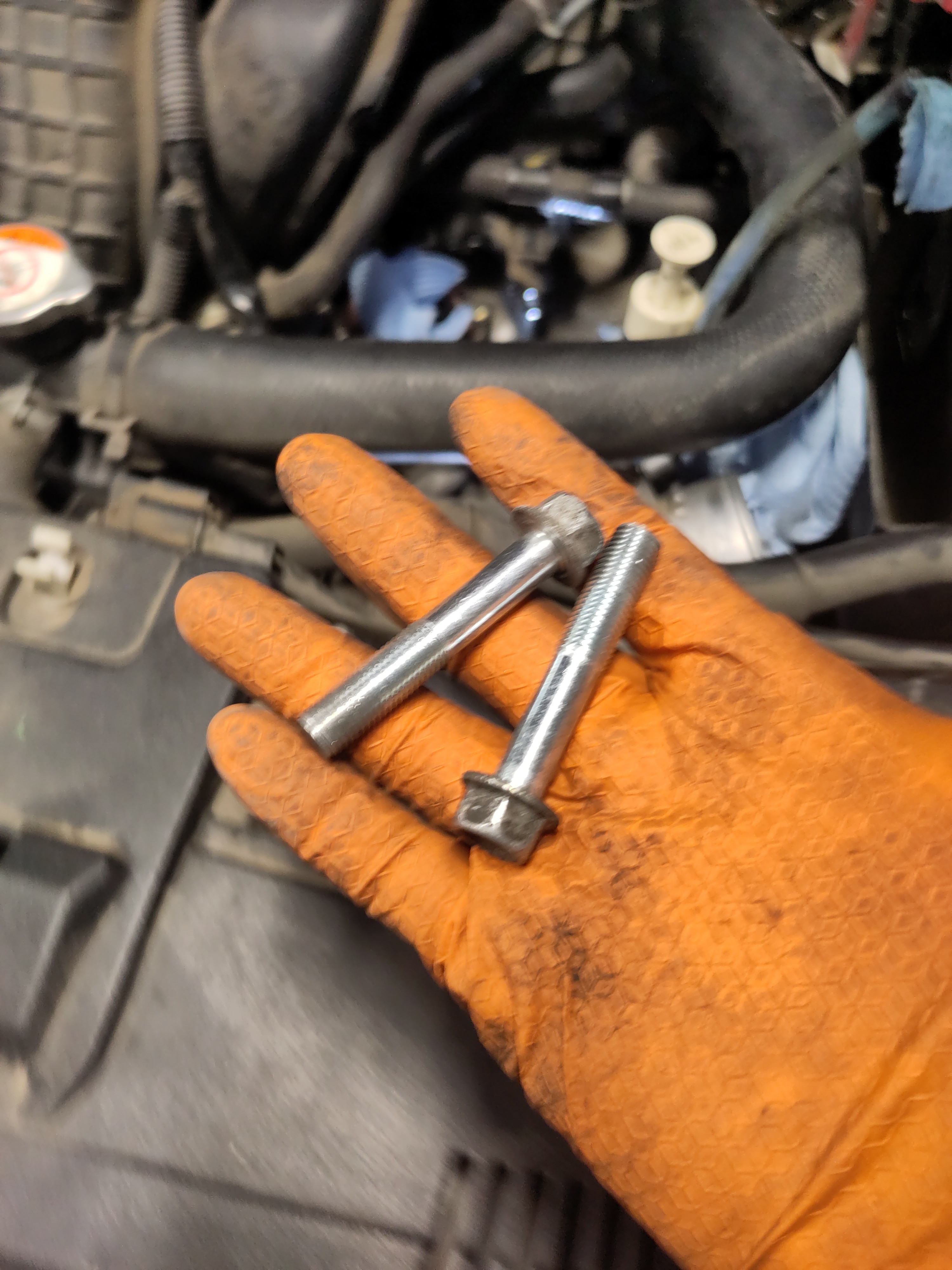
- With the removal of the bottom 14mm bolt, it is time to remove the starter. It can be a tricky and arduous to remove the starter it will require some rotation and pull. It is important to note that the way you pull it out should be remembered because that is how you are gonna install the new starter as far as the range of motion and rotation. Begin by pushing up while pulling it out from the hole. At the same time, the back end of the starter will be needed to swing out towards you close to a 90 degree angle. There is a full tutorial video in the references if it becomes rather difficult to remove it. The range motion and the concurrent movements can make it difficult to remove it because of how compact everything is.
Preparation & Installation:
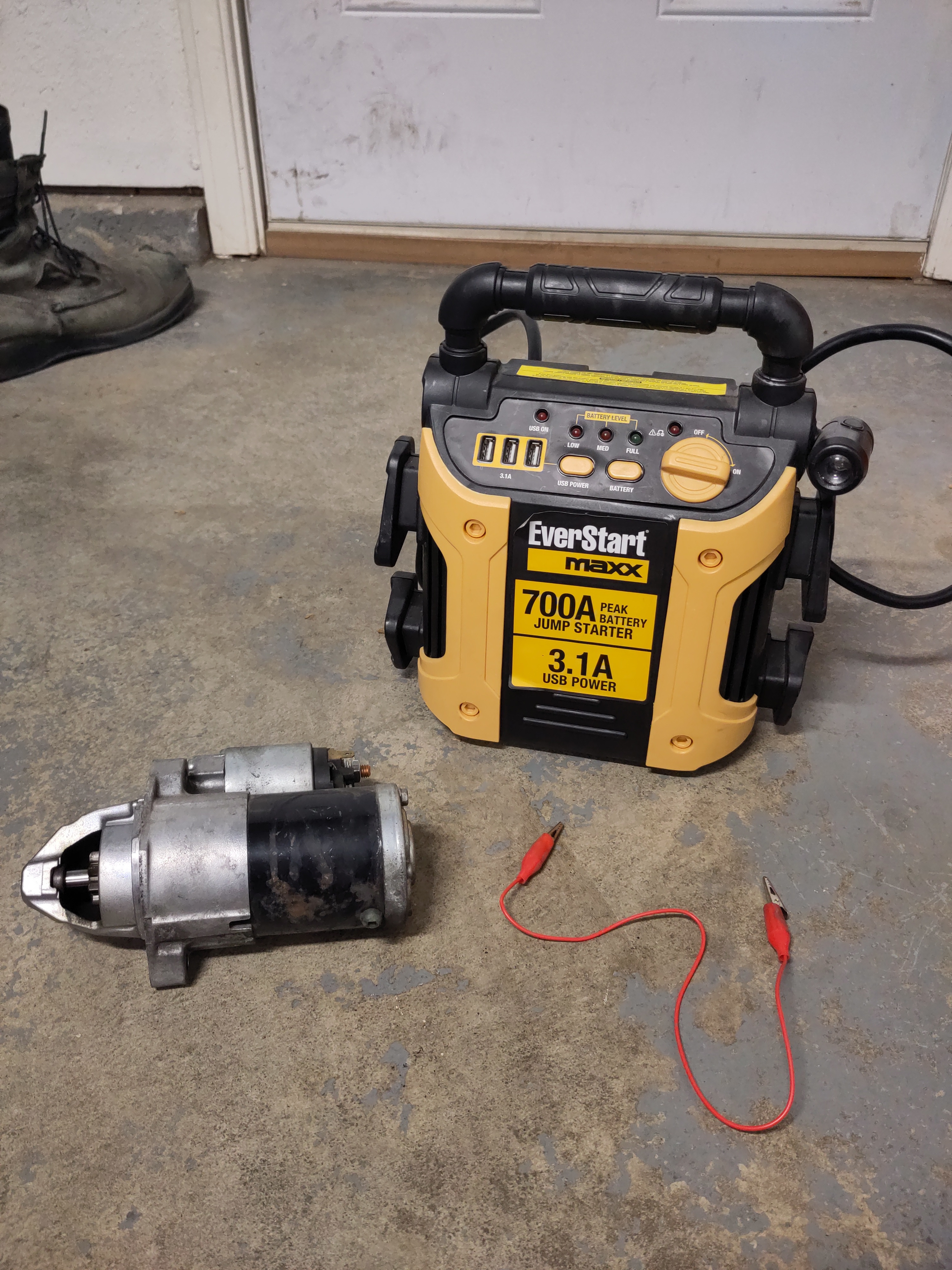
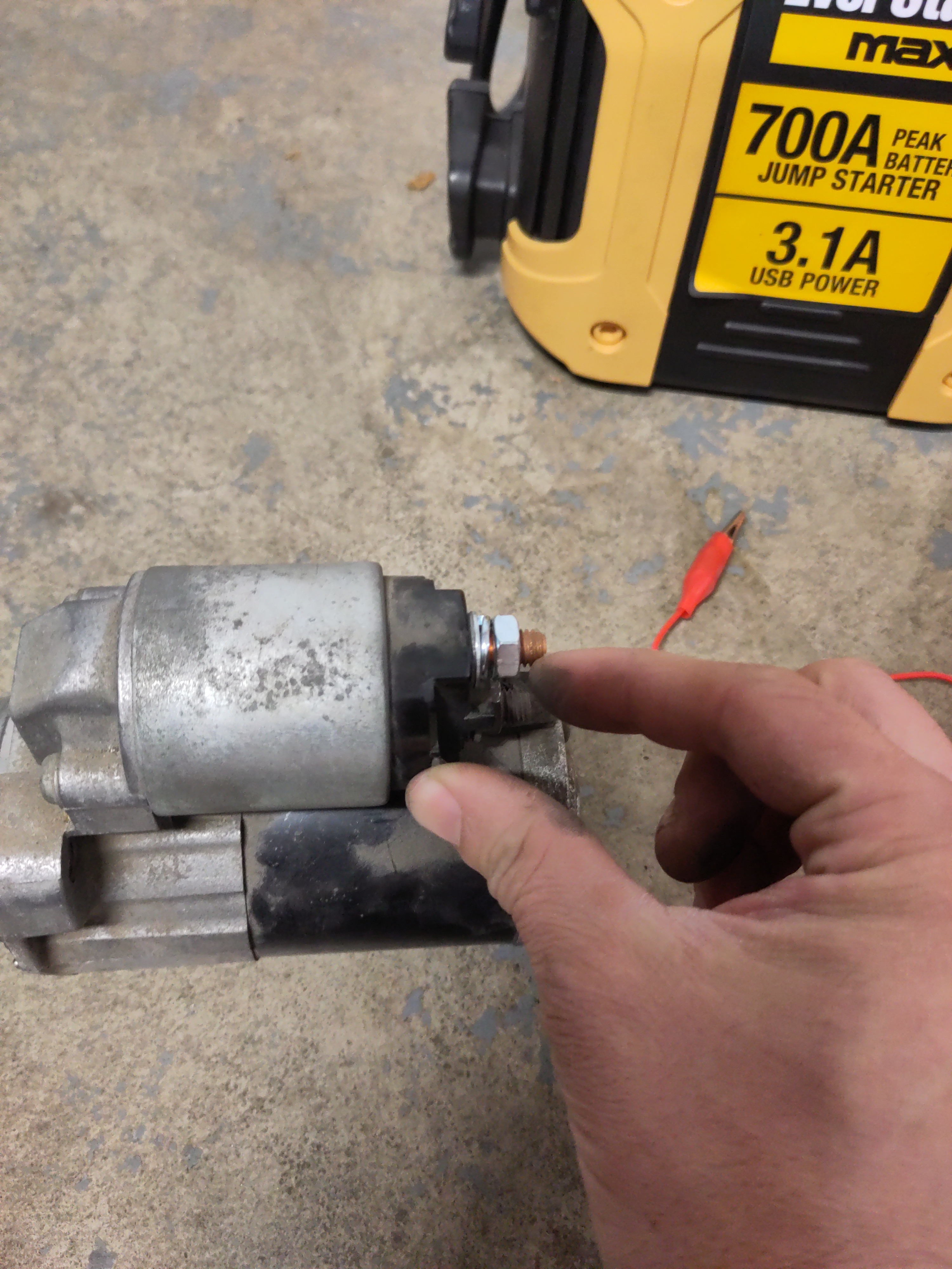
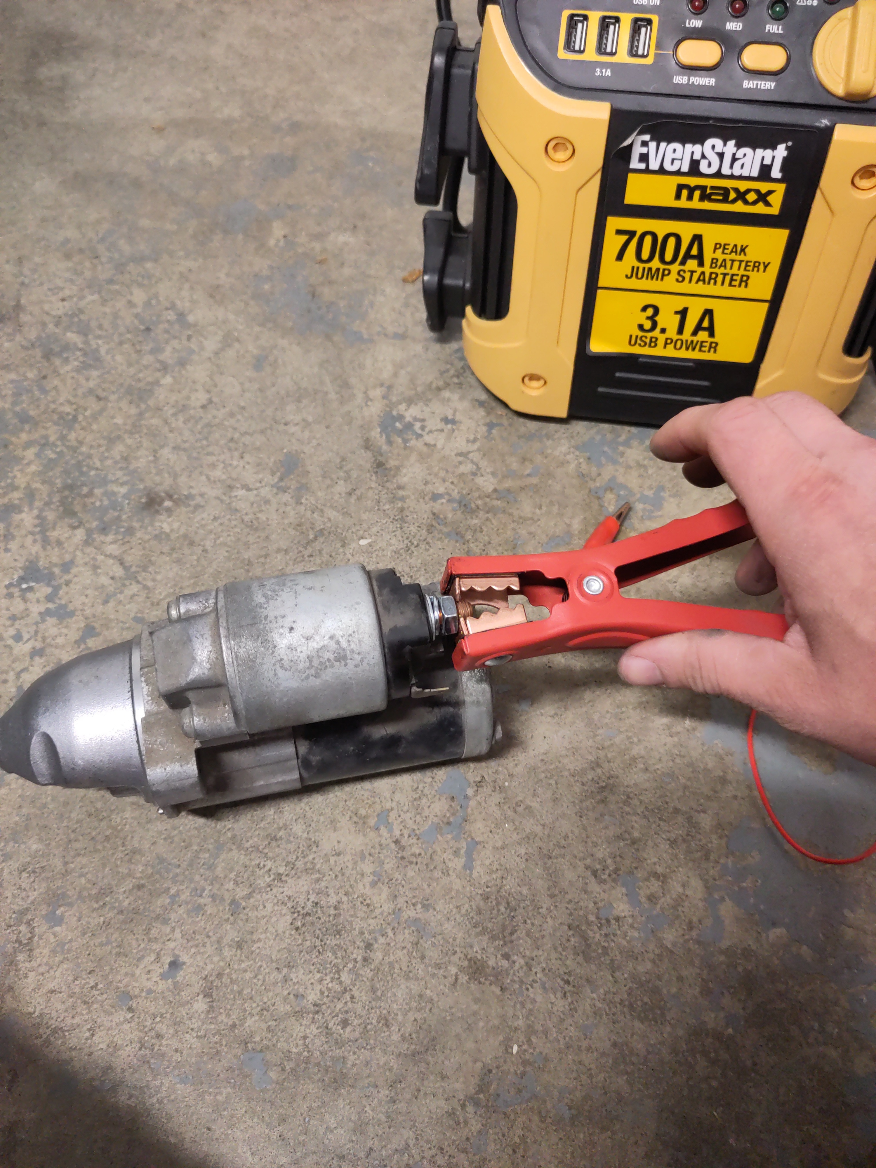
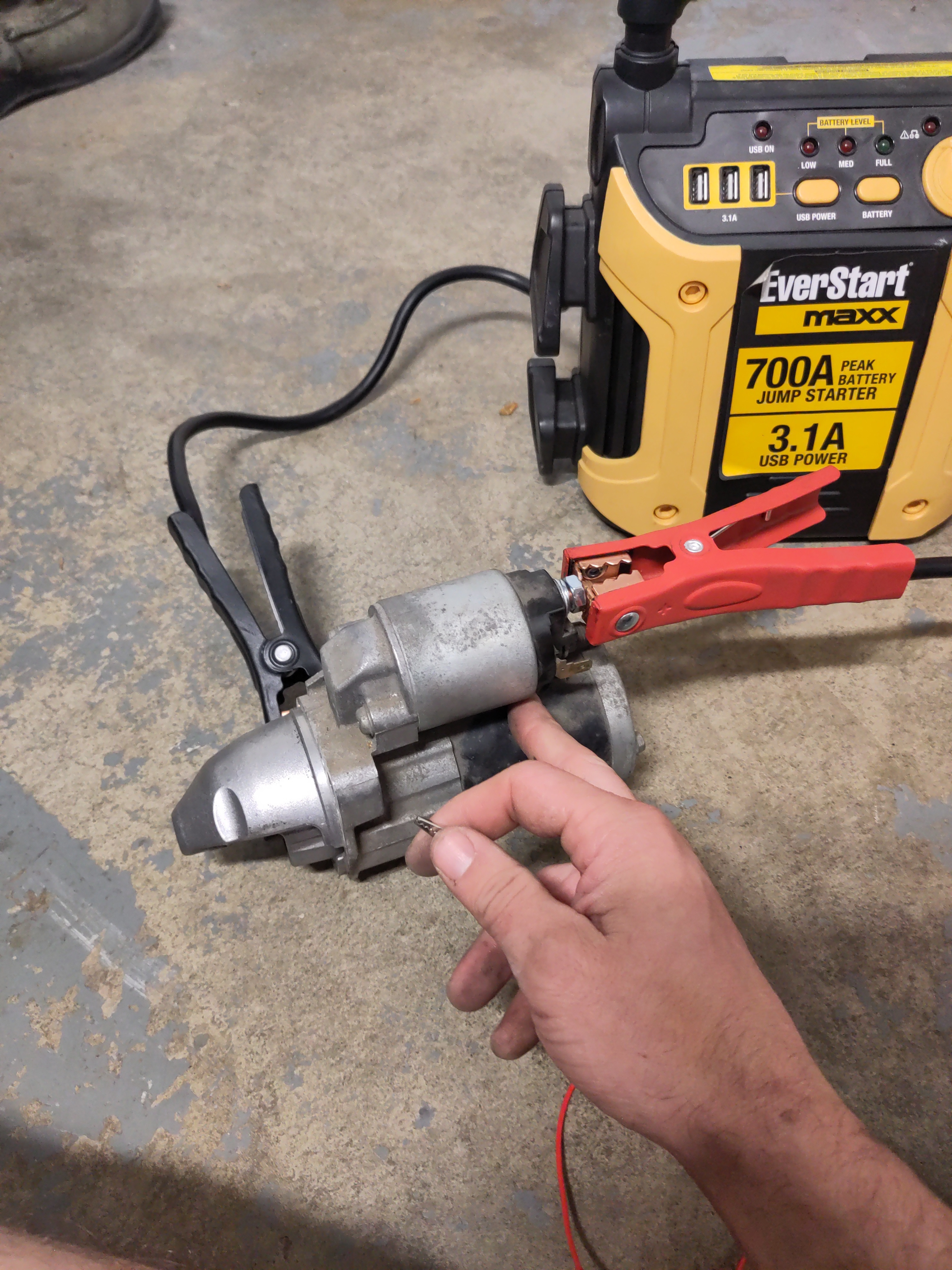
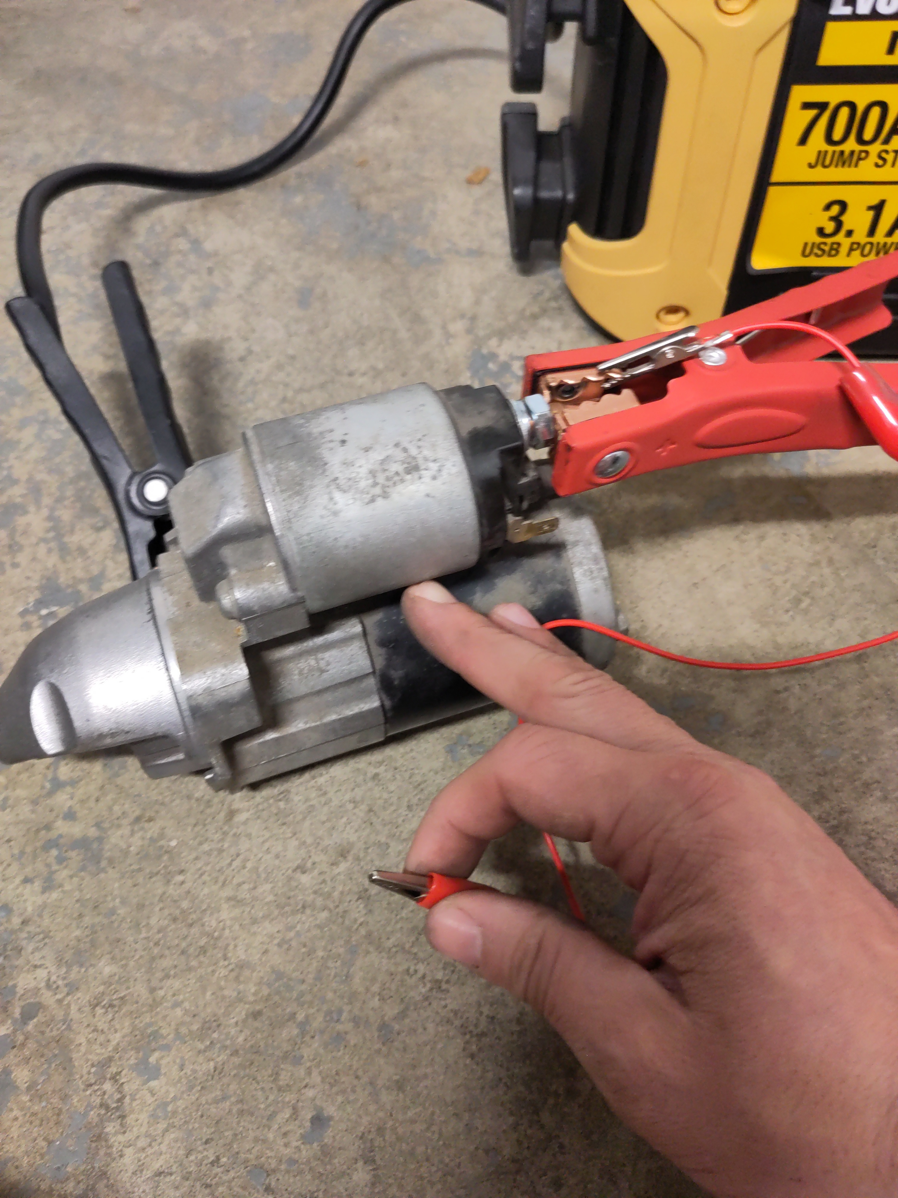
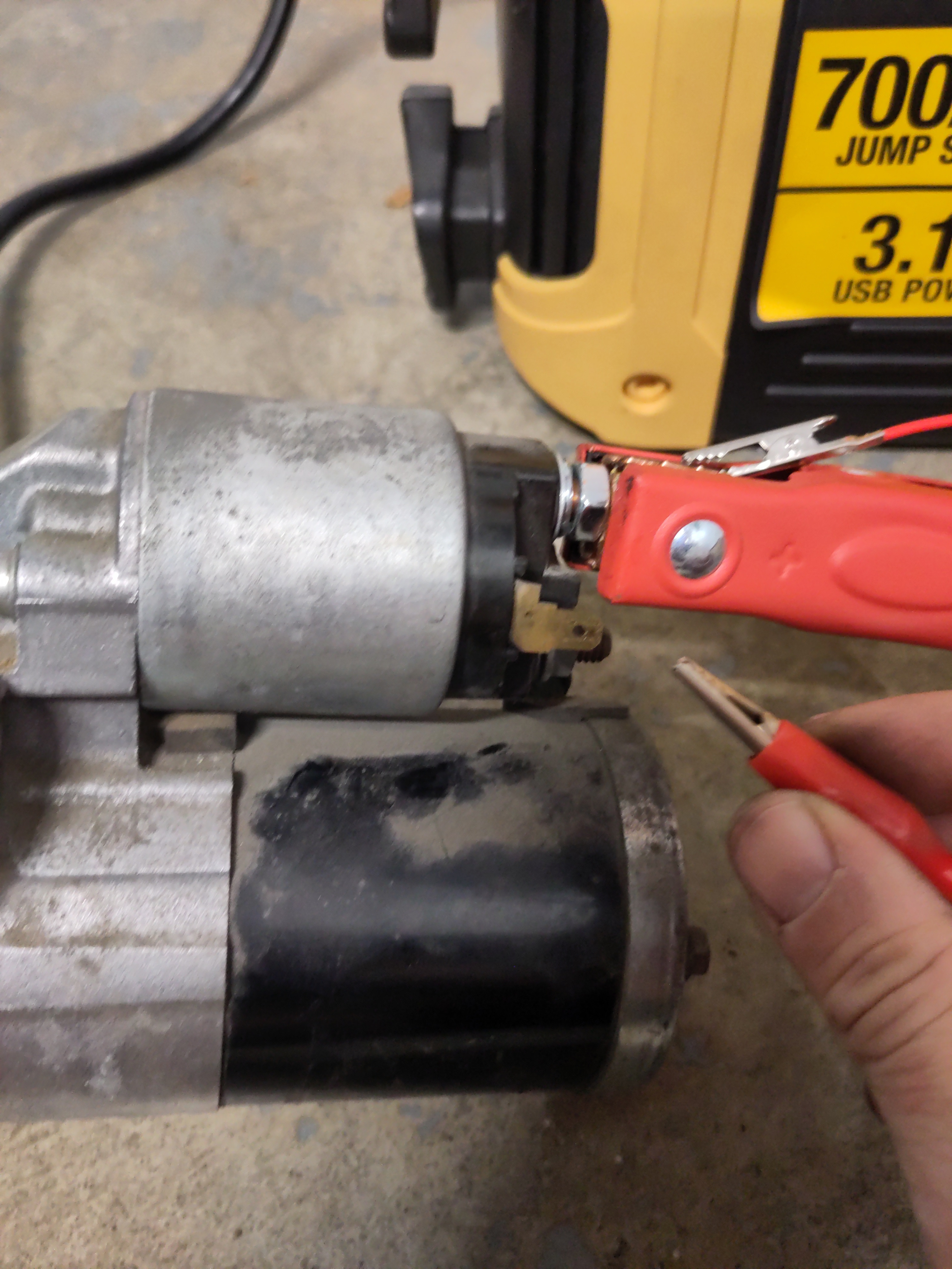
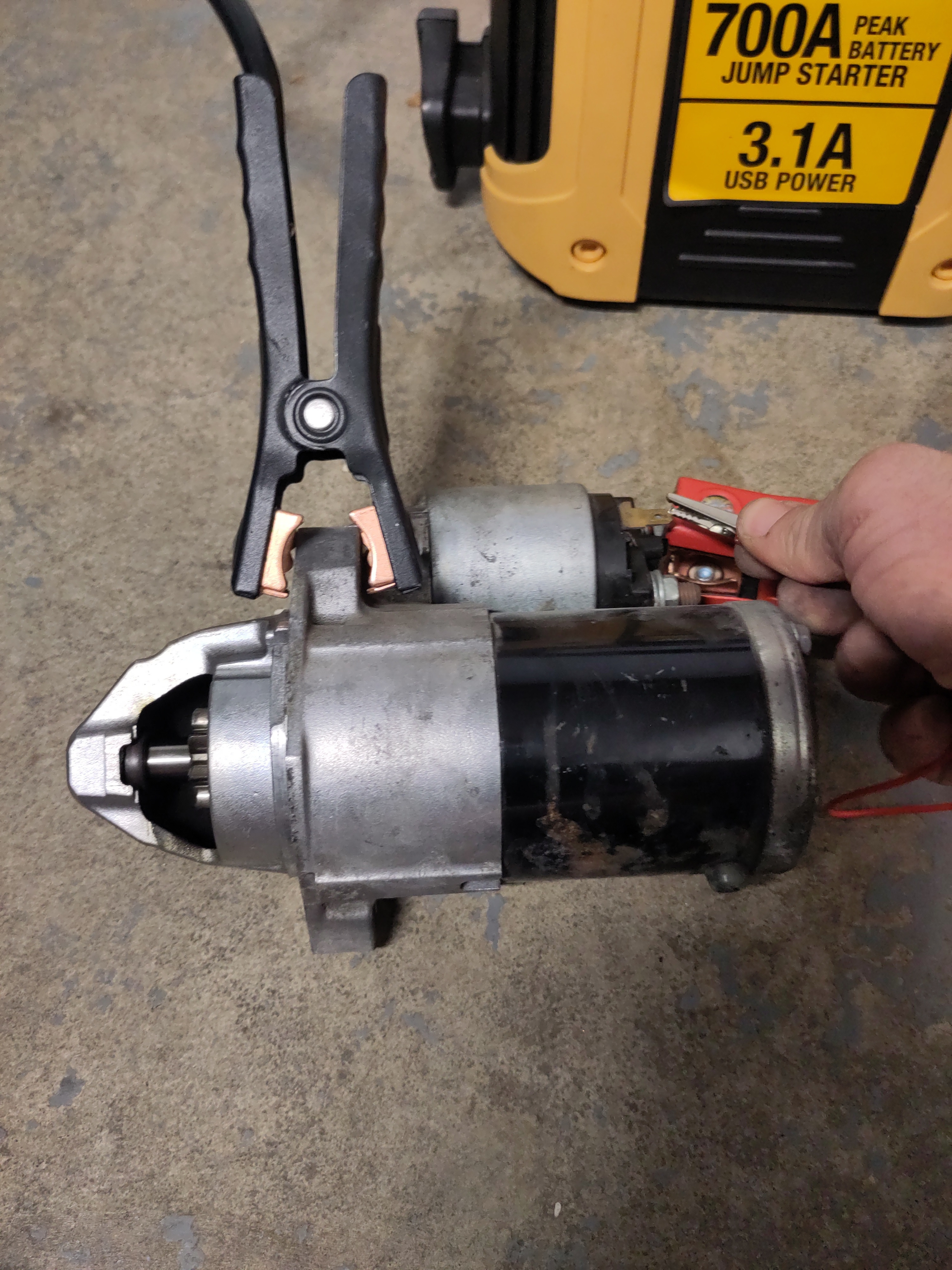
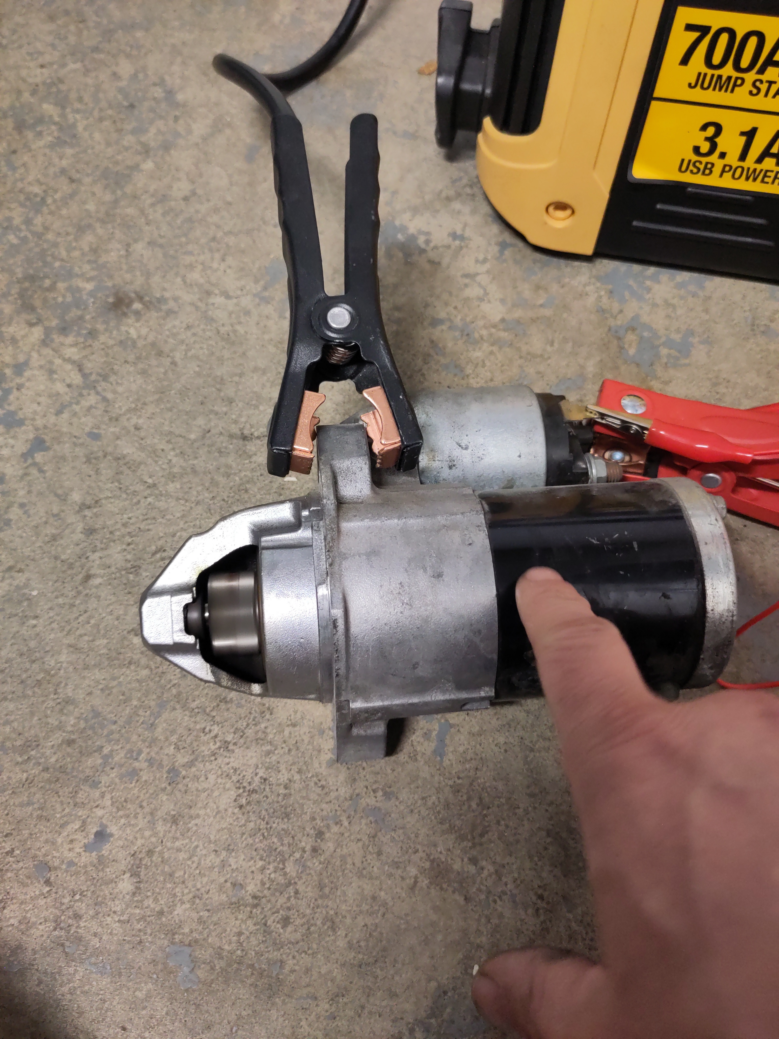
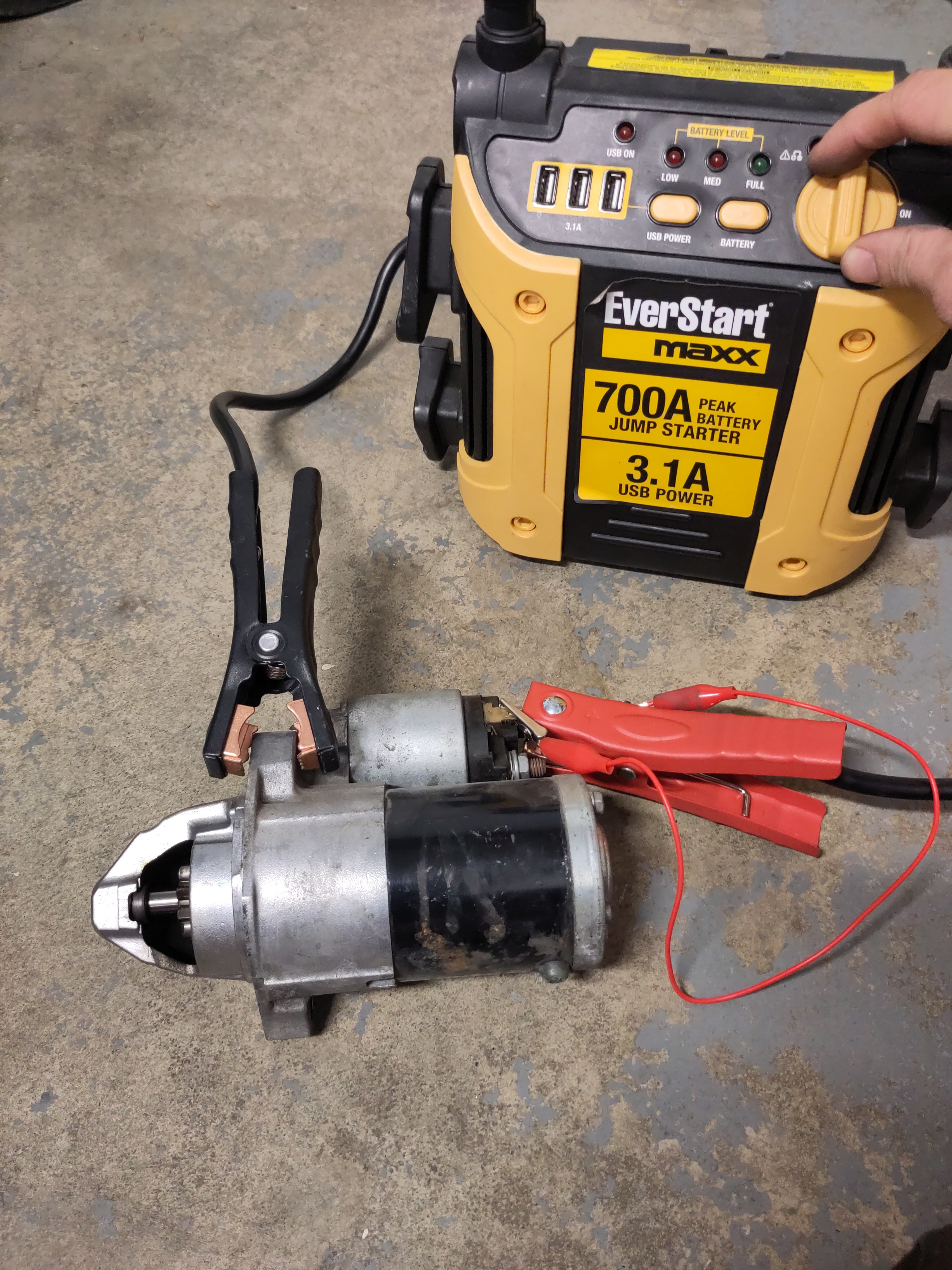
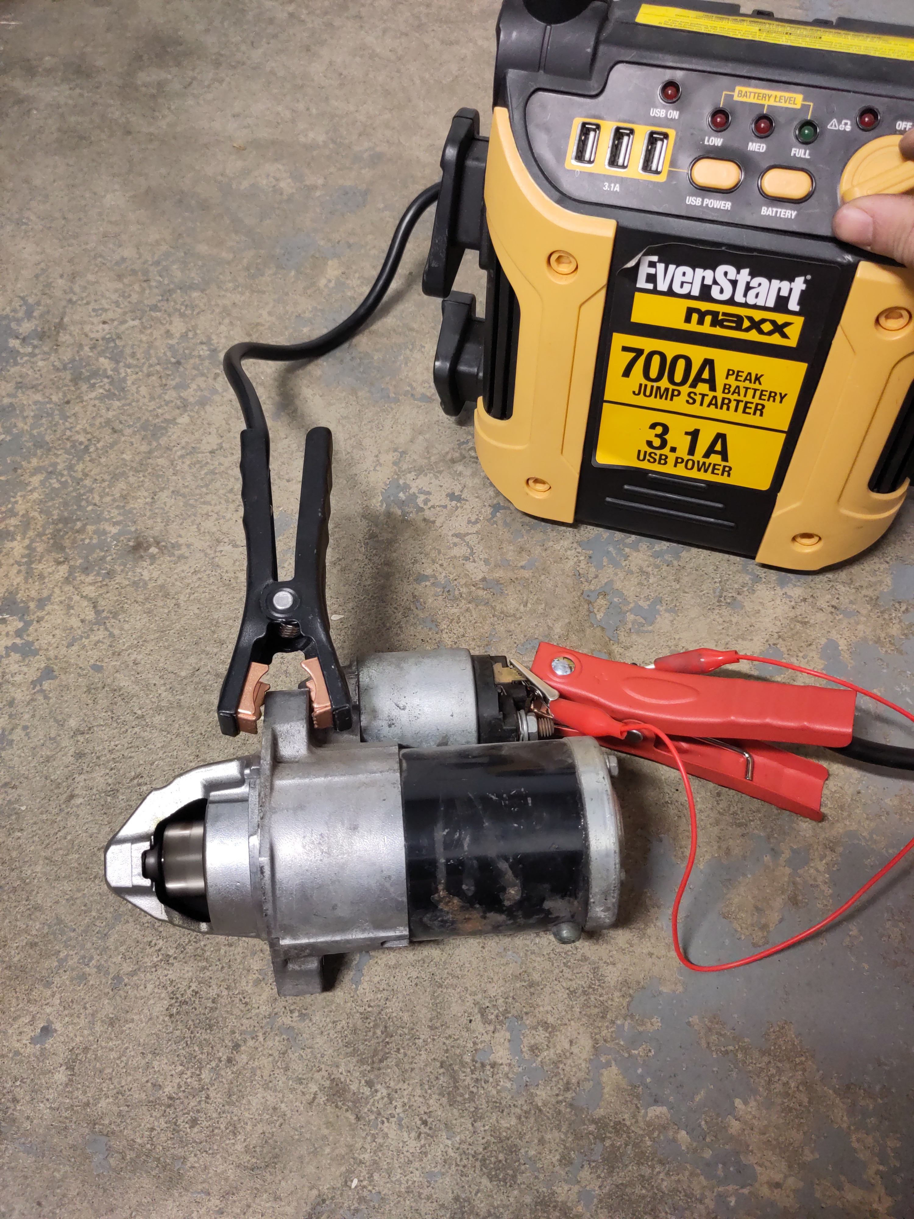
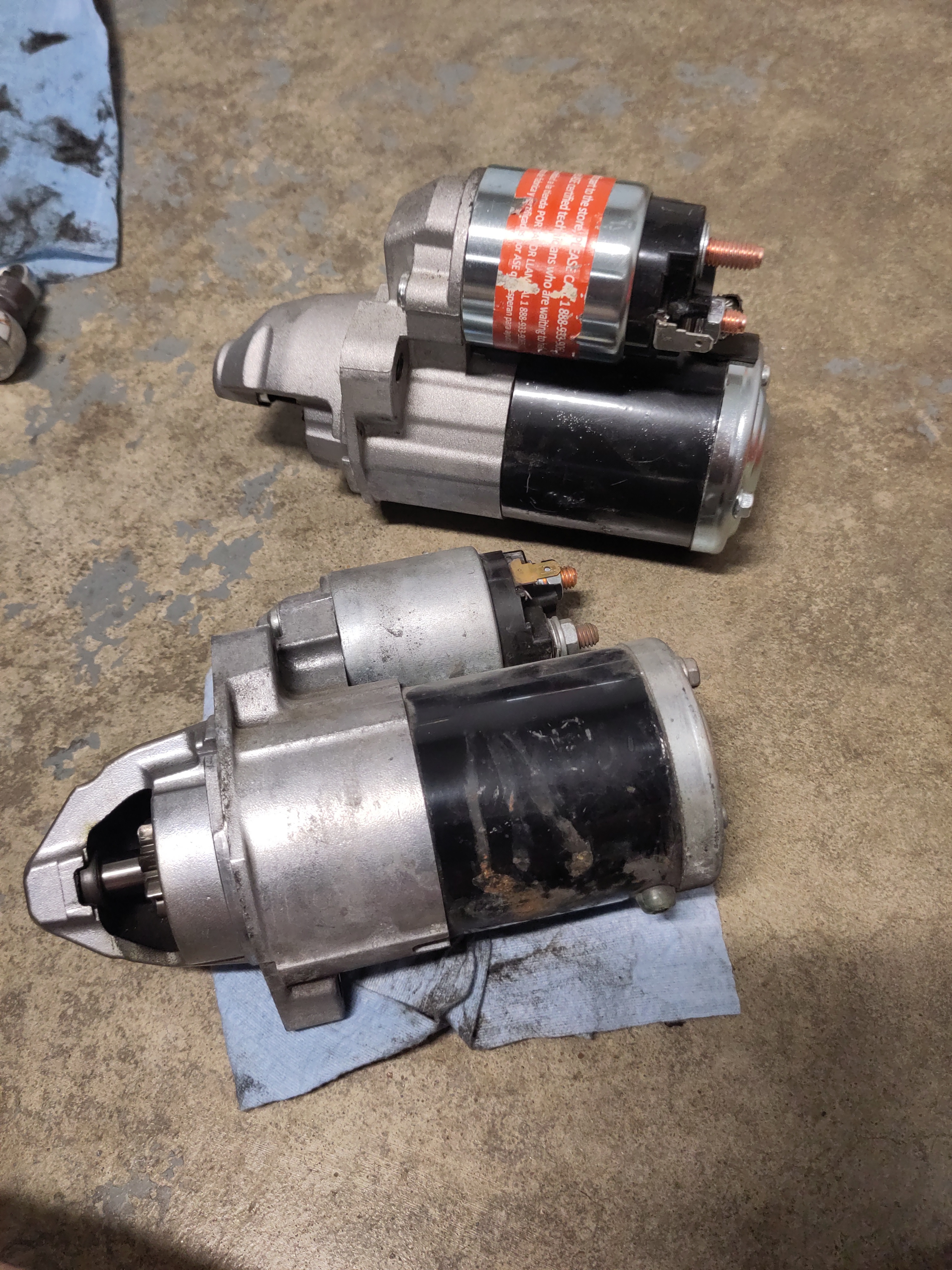
Now it is time to take the new starter and begin to install it. However, it's never a bad idea to compare the old starter to the new one just to ensure compatibility and the condition. The new starter being installed into the 2013 Lancer ES is a re-manufactured/refurbished. It is good to inspect the new one for any signs of wear and tear. The next section of the tutorial will show to test the starter to see if it is fully functioning.
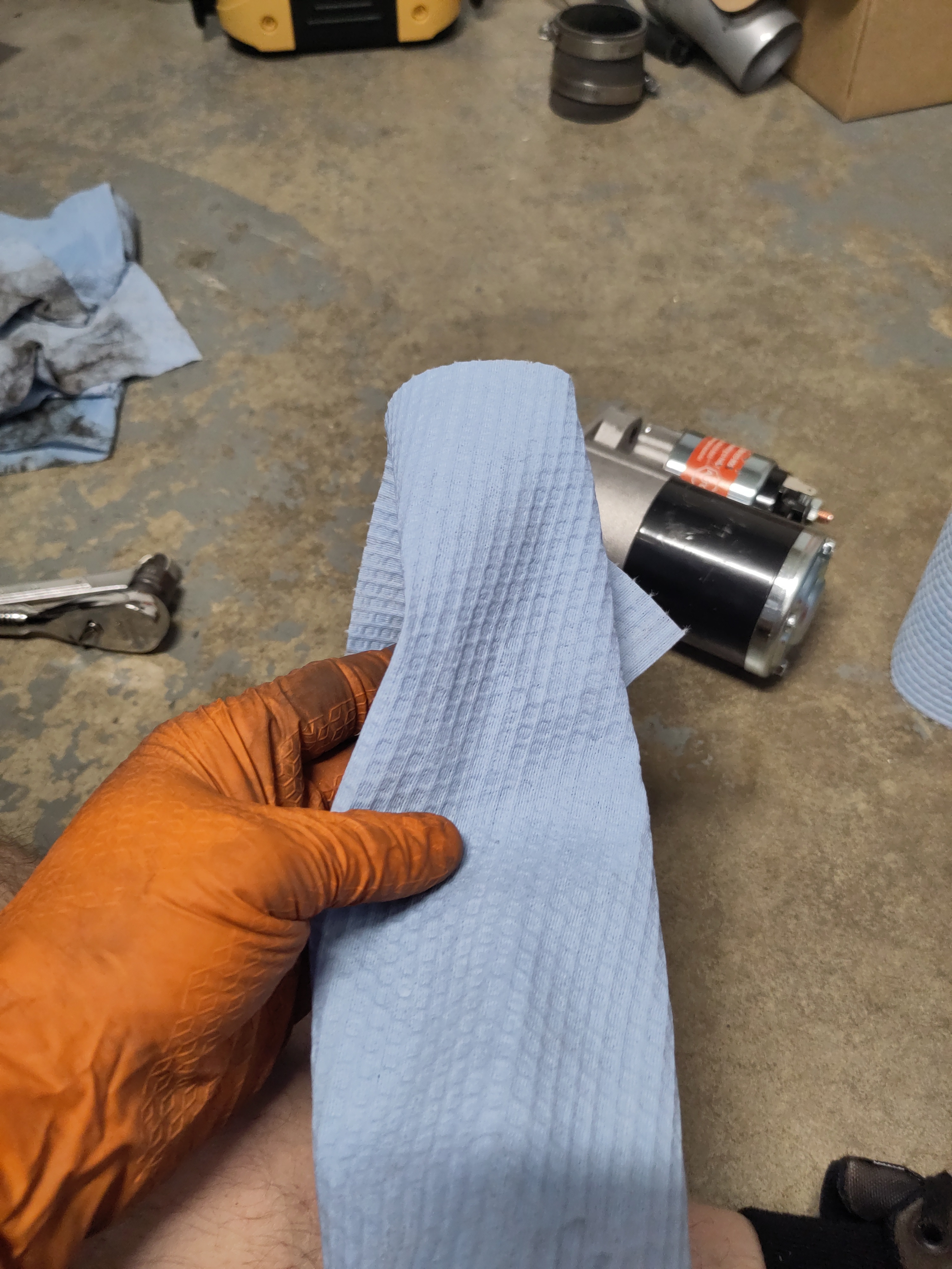
- Prior to installing the new starter, it is a good idea to clean the surrounding area of where the starter will be seated by using a dry clean paper towel. Also, using a dry clean paper towel, wipe the inside of the entry point of where the starter is seated which has exposure to the flywheel. Wipe all that down to your best of ability remove any debris.
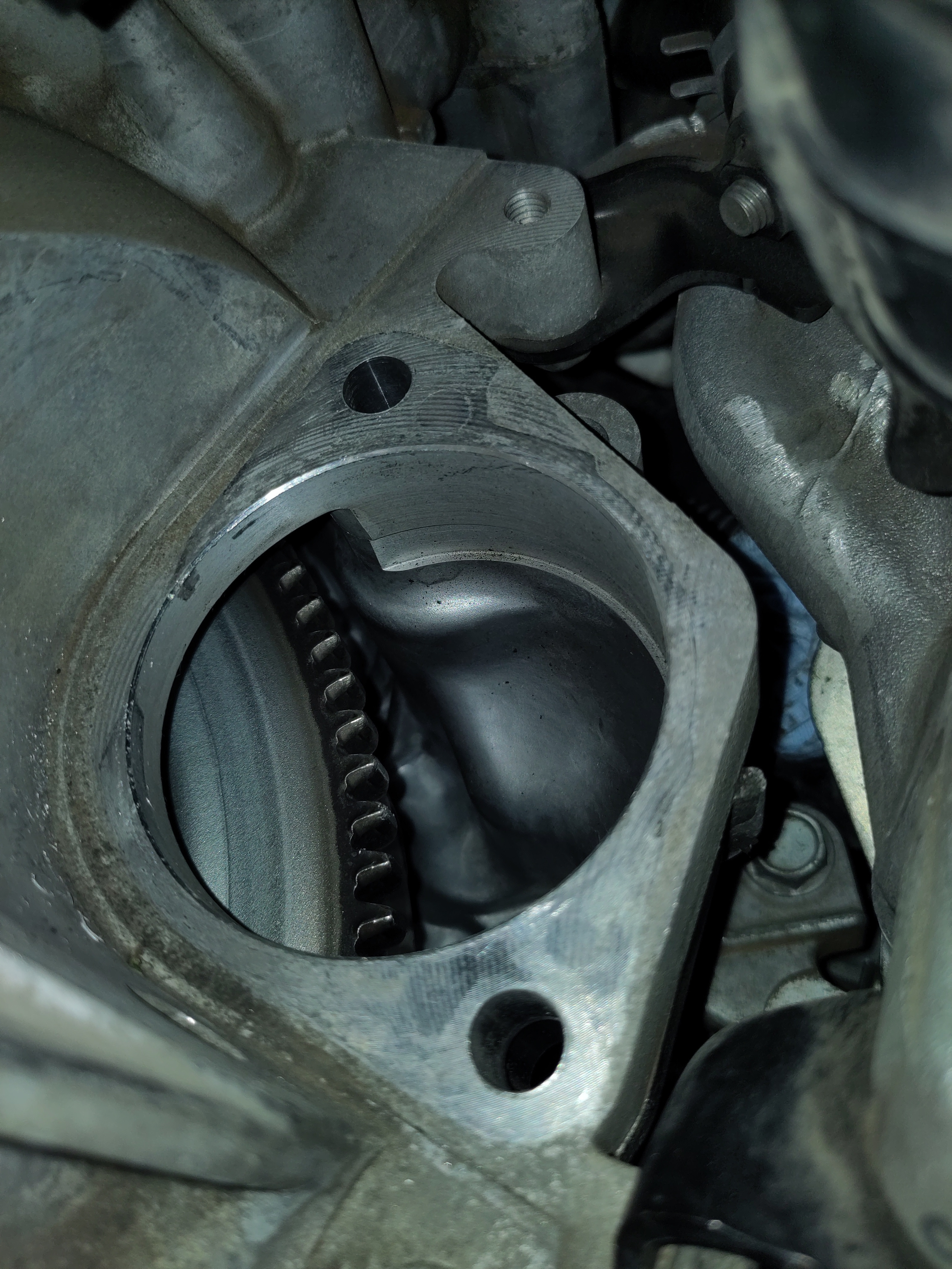
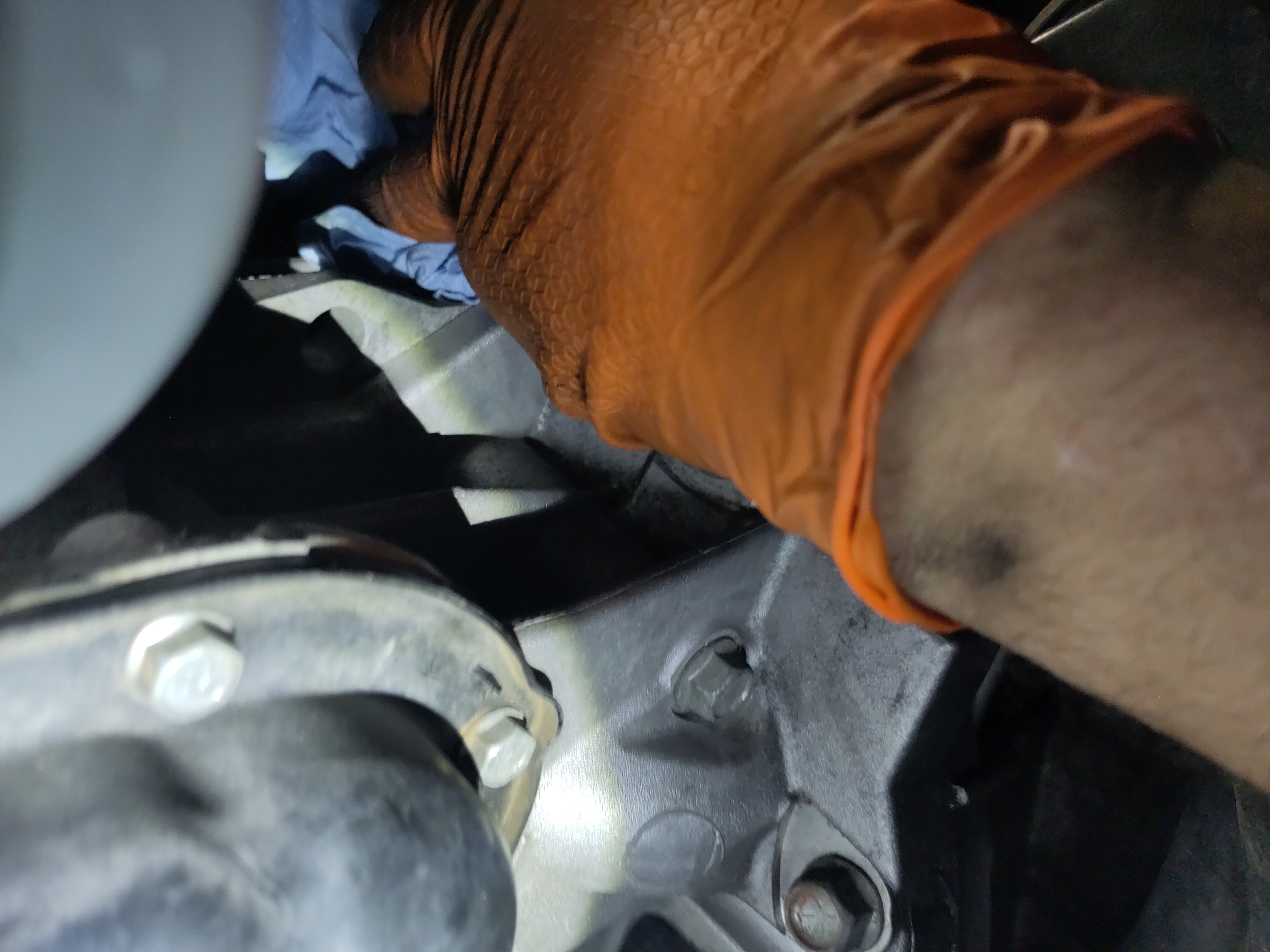
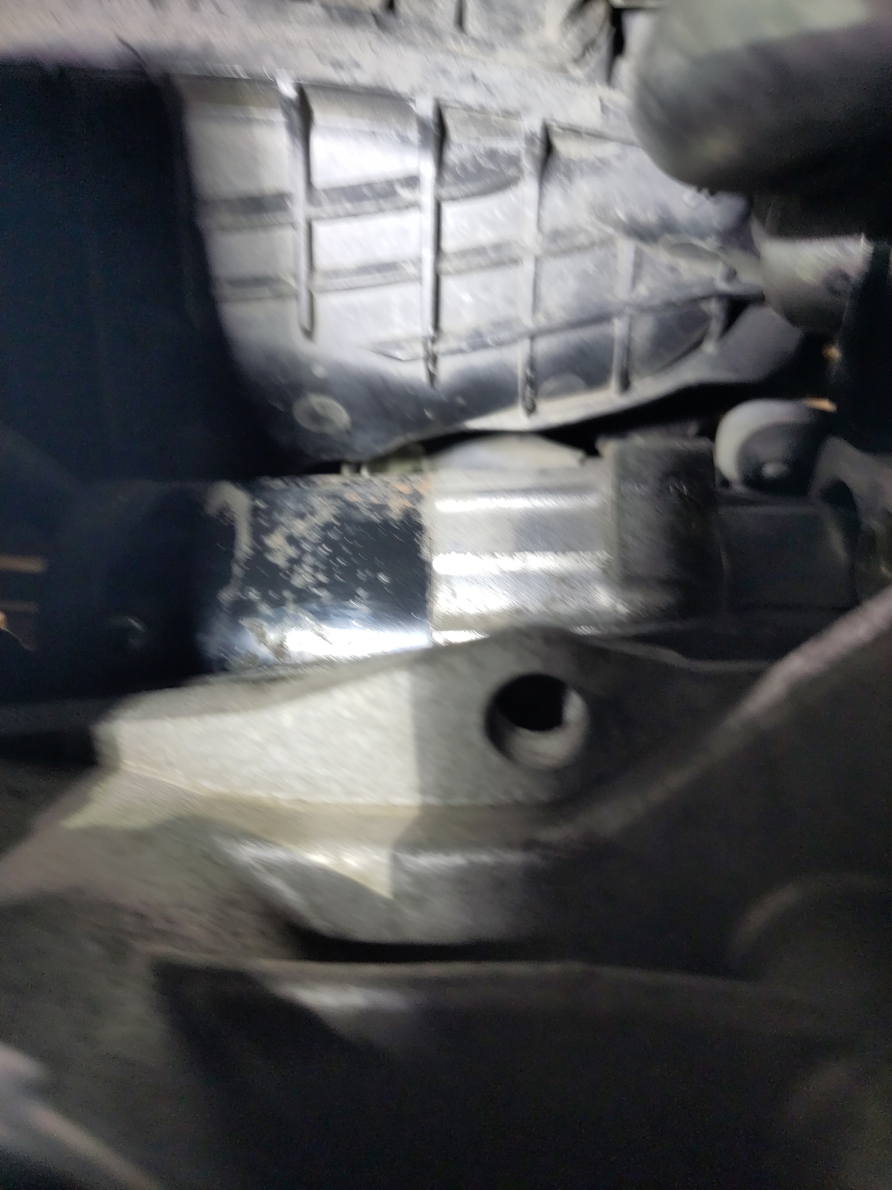
- Next install the starter the same way you removed it by having the solenoid side horizontal when initial going then rotating upwards to get the starter to be properly seated. It will take some wiggling and play just be determined and patient. Watch the full tutorial and pay much attention to the range of motion and rotations to successful placement of the starter.
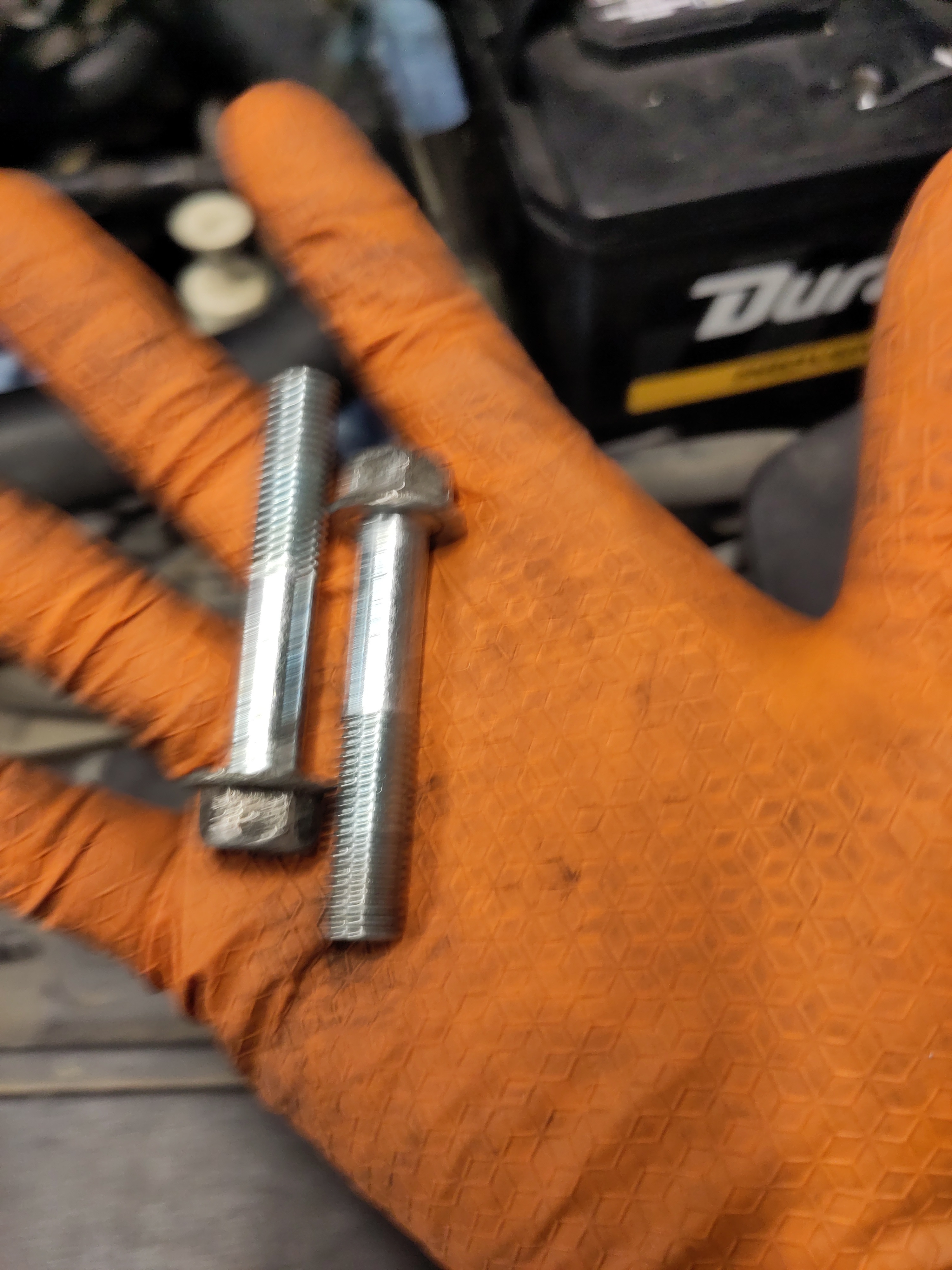
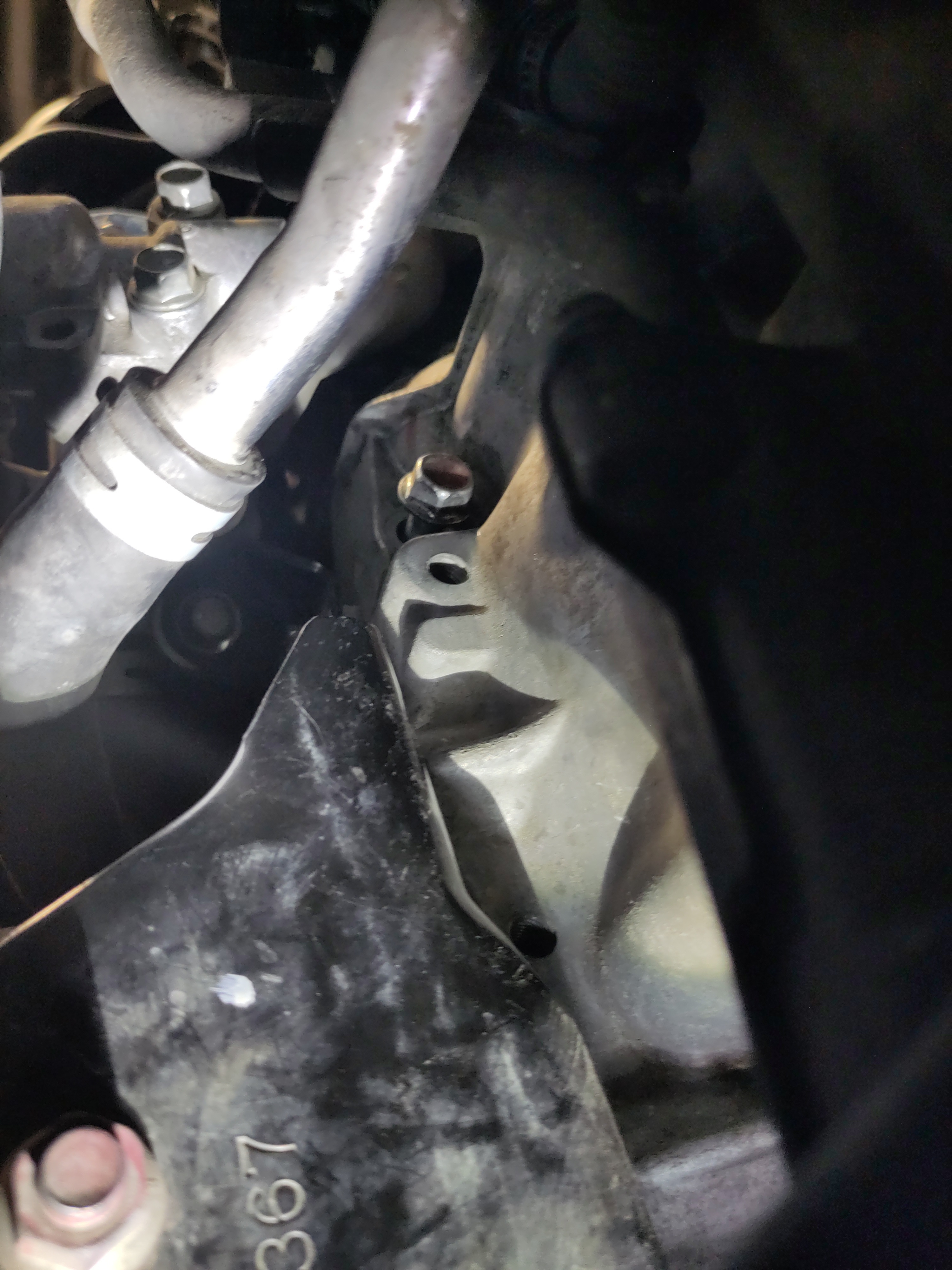
- With the starter properly mounted it is now time to take 14mm bolts and thread them into the holes by hand while compressing the starter to the transmission ensuring the bolts are in alignment with the holes of the starter. Just hand thread the bolts in because the next step will be installing the electrical connections
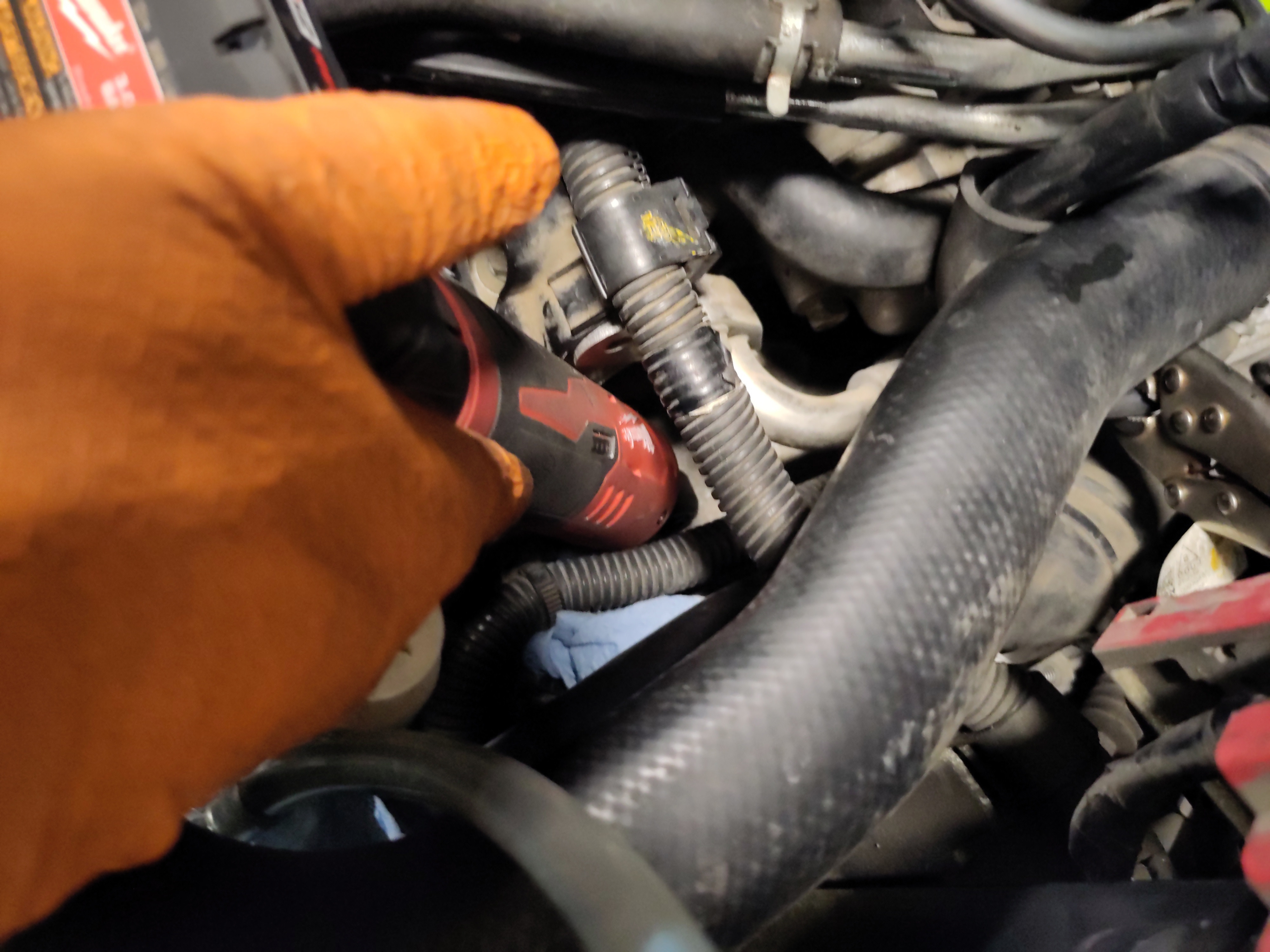
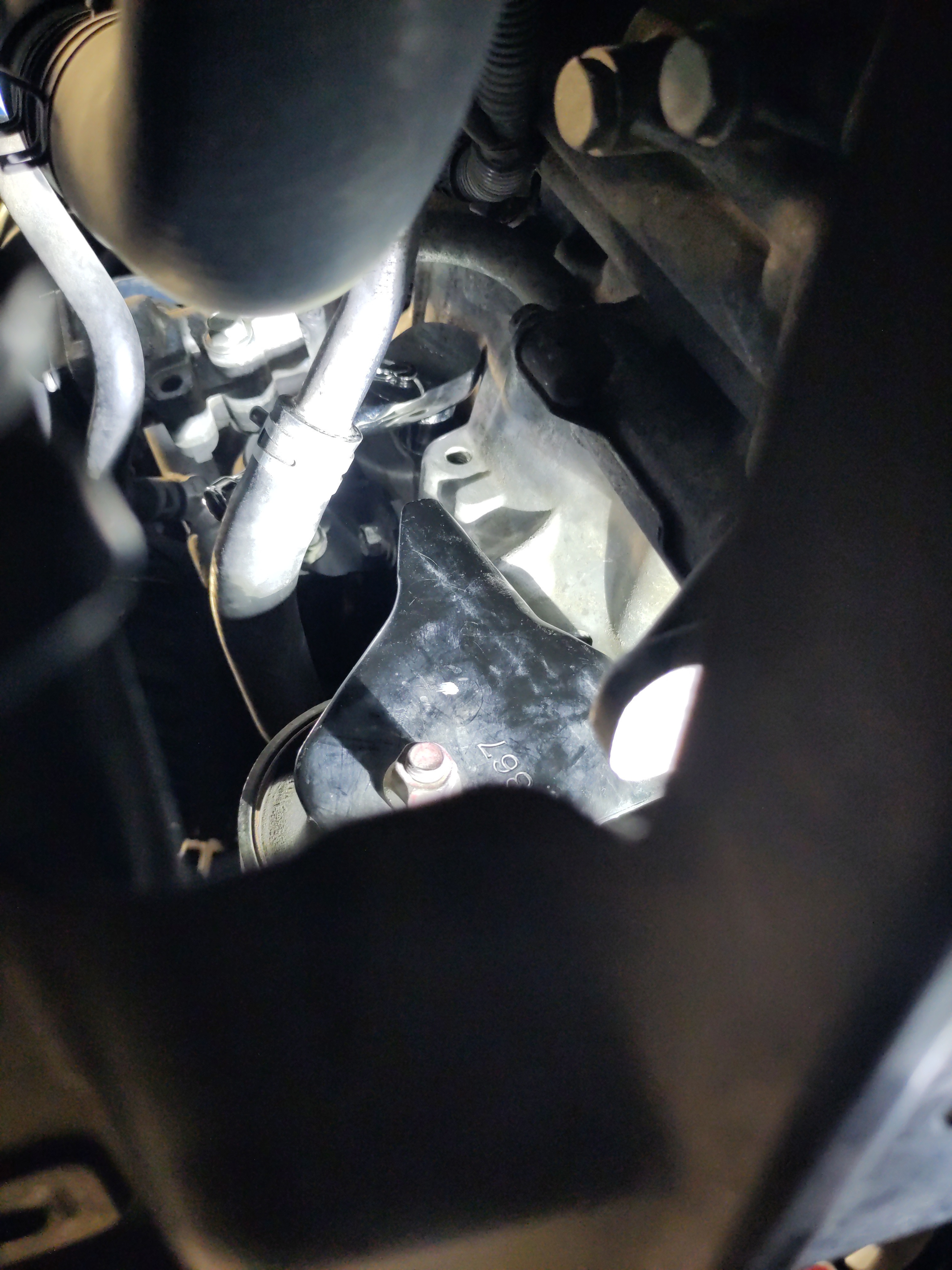
- Place your arm in between the manifold like in step 19 of the removal section, and connect the signal electrical connection to the new starter.
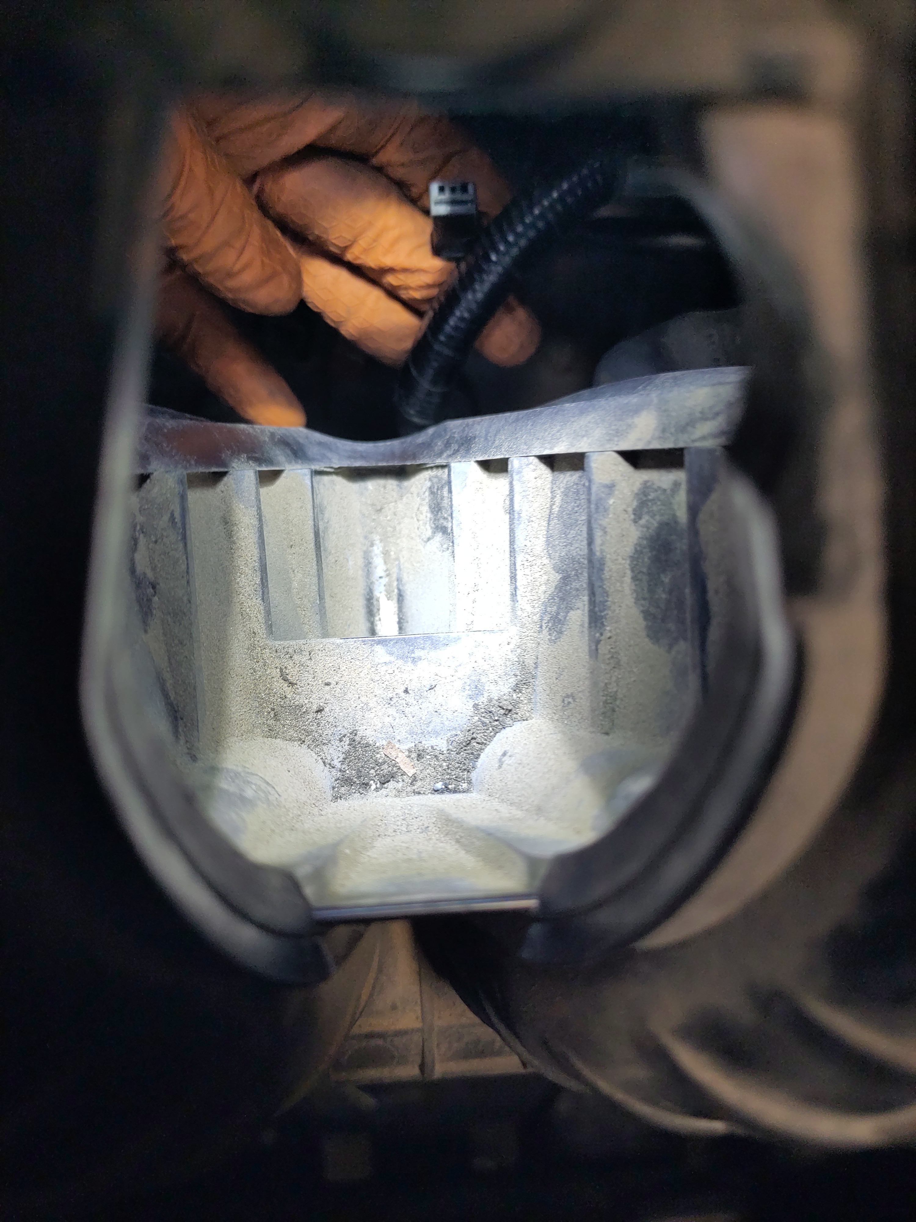
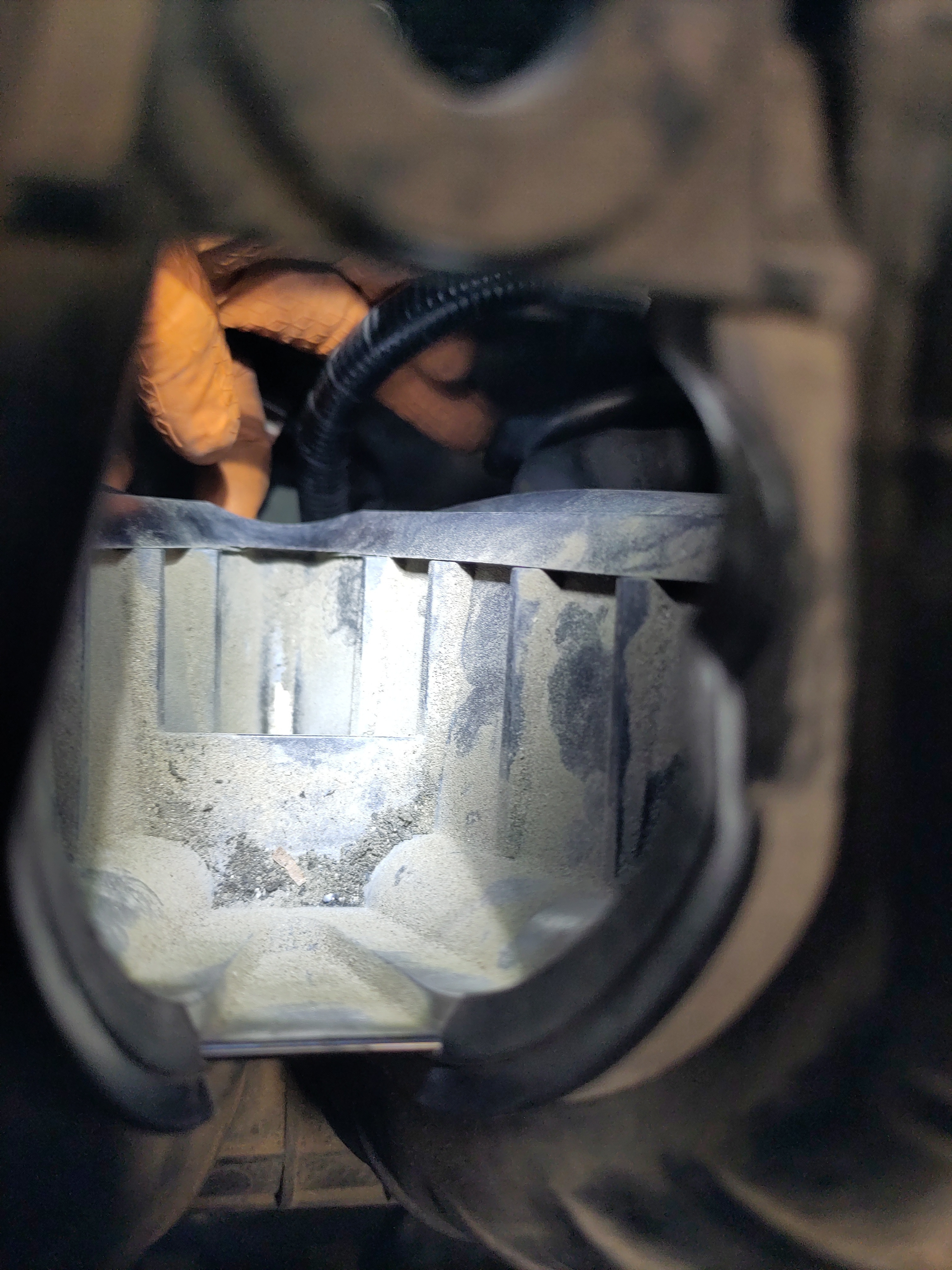
- Now put the positive electrical connection wire onto the threaded terminal of starter.It is recommended to use a 3/8" drive shallow 12mm socket with an extension to hand thread the 12mm nut before using a socket wrench. I found this to be better than doing it by hand because of how awkward it is then the risk of dropping the nut. The nut being placed into the shallow socket with extensions prevents this so the focus can be just getting it initially threaded. Once it is threaded on, go a head and use a socket wrench to continue on torquing it down so it has a secure connection. Then place the boot over the connection to protect it.
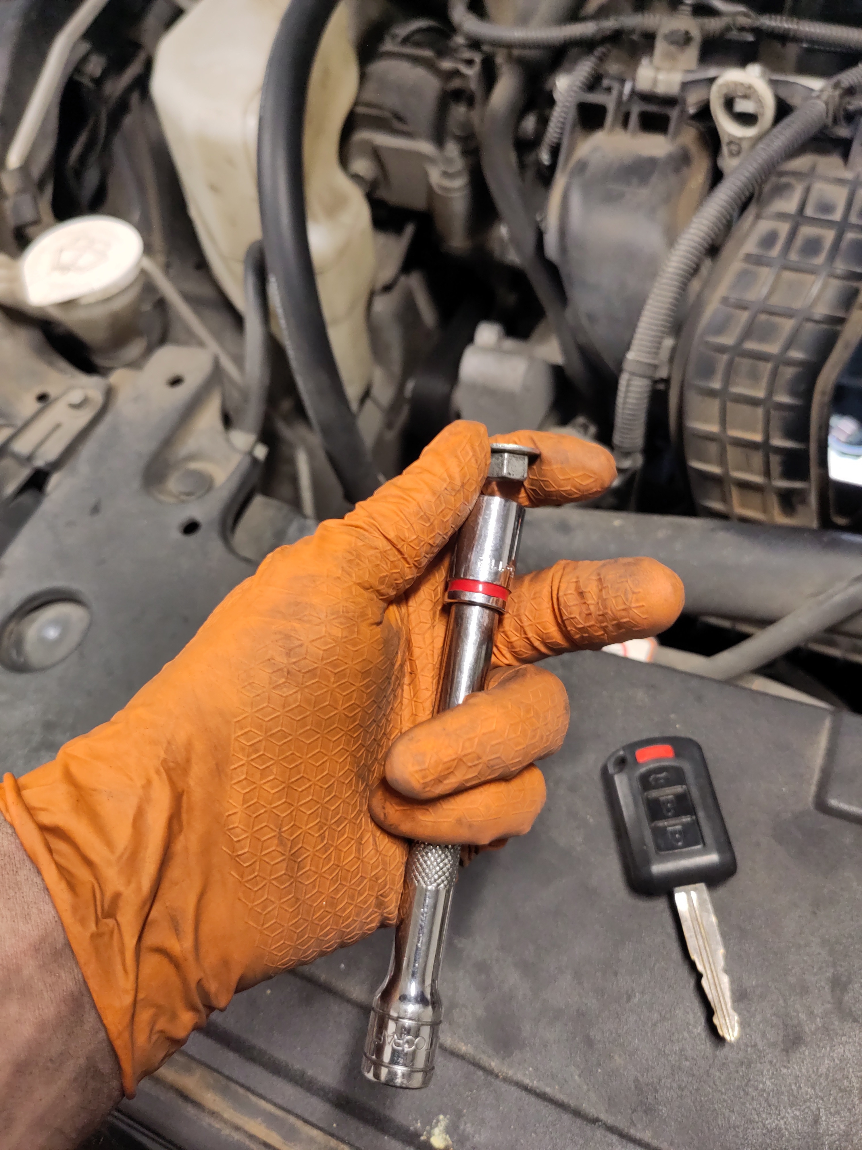
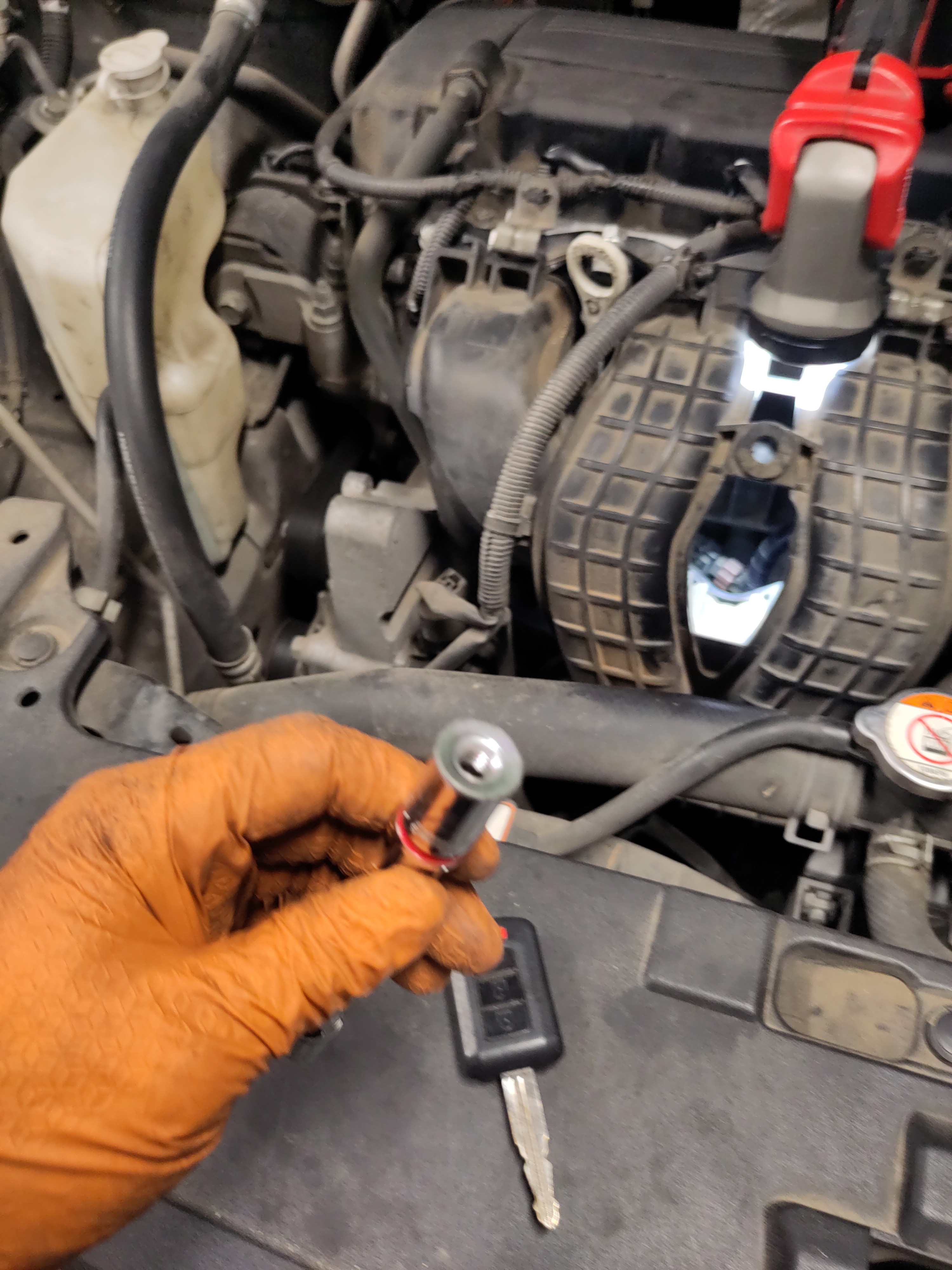
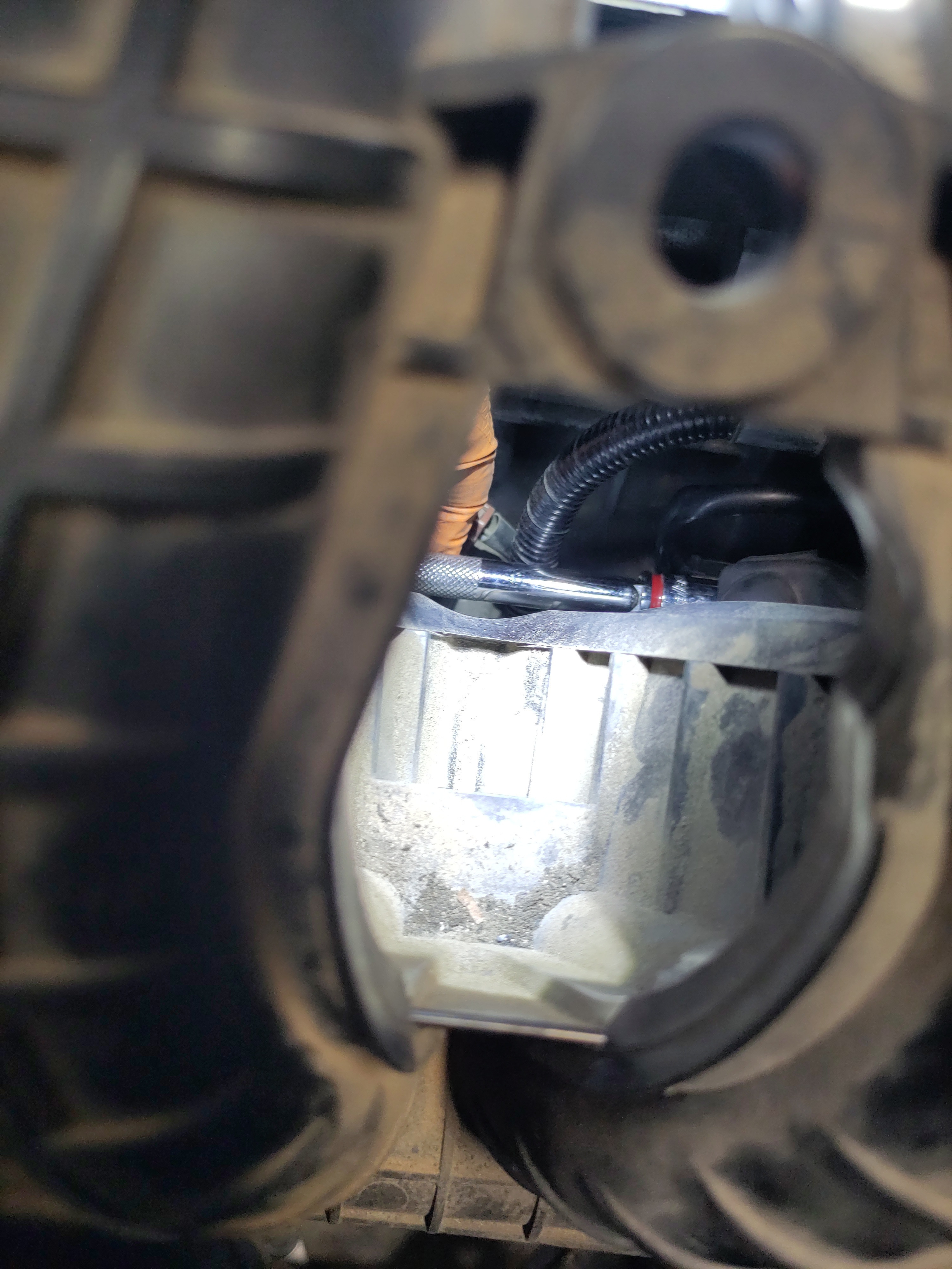
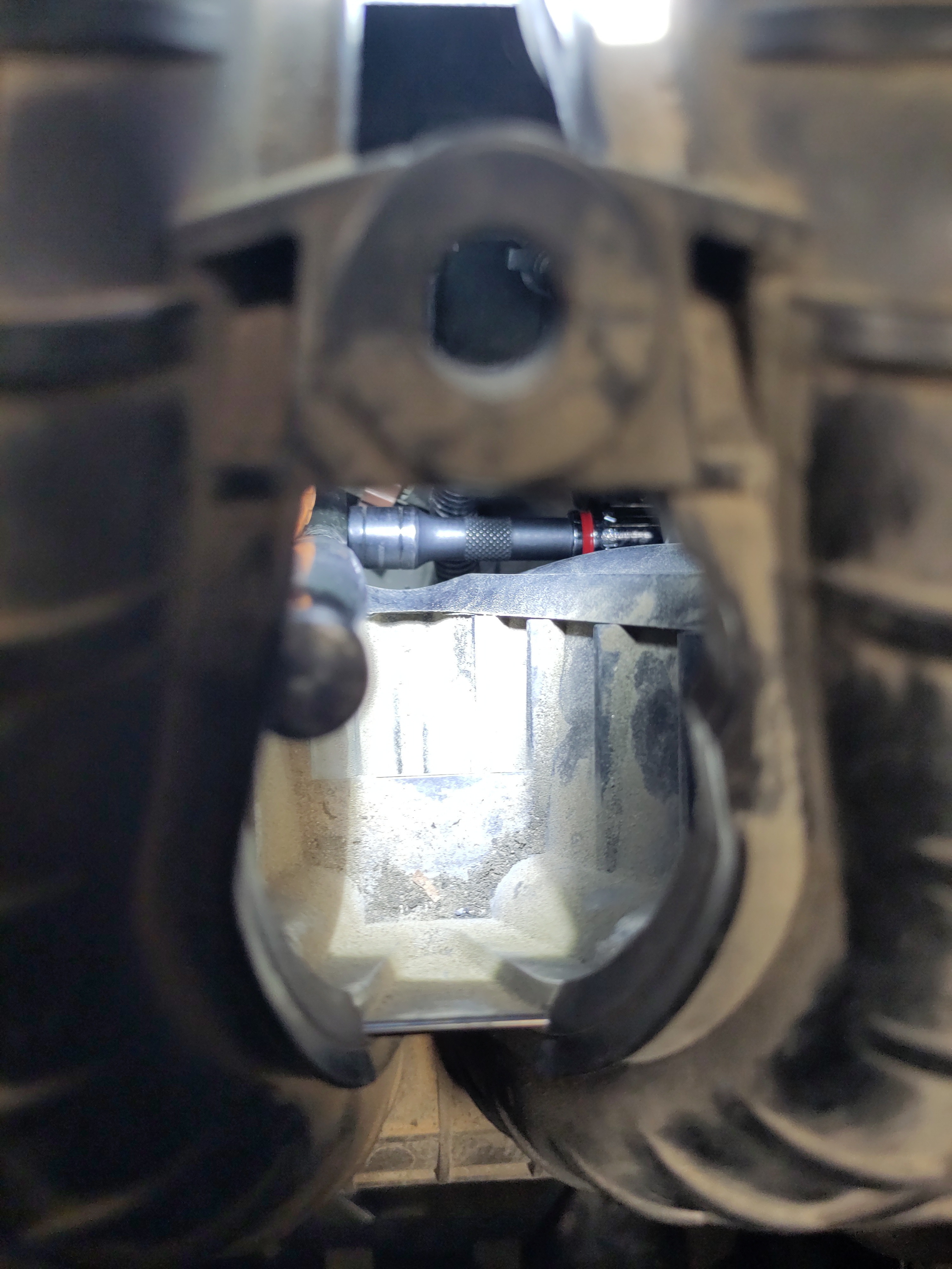
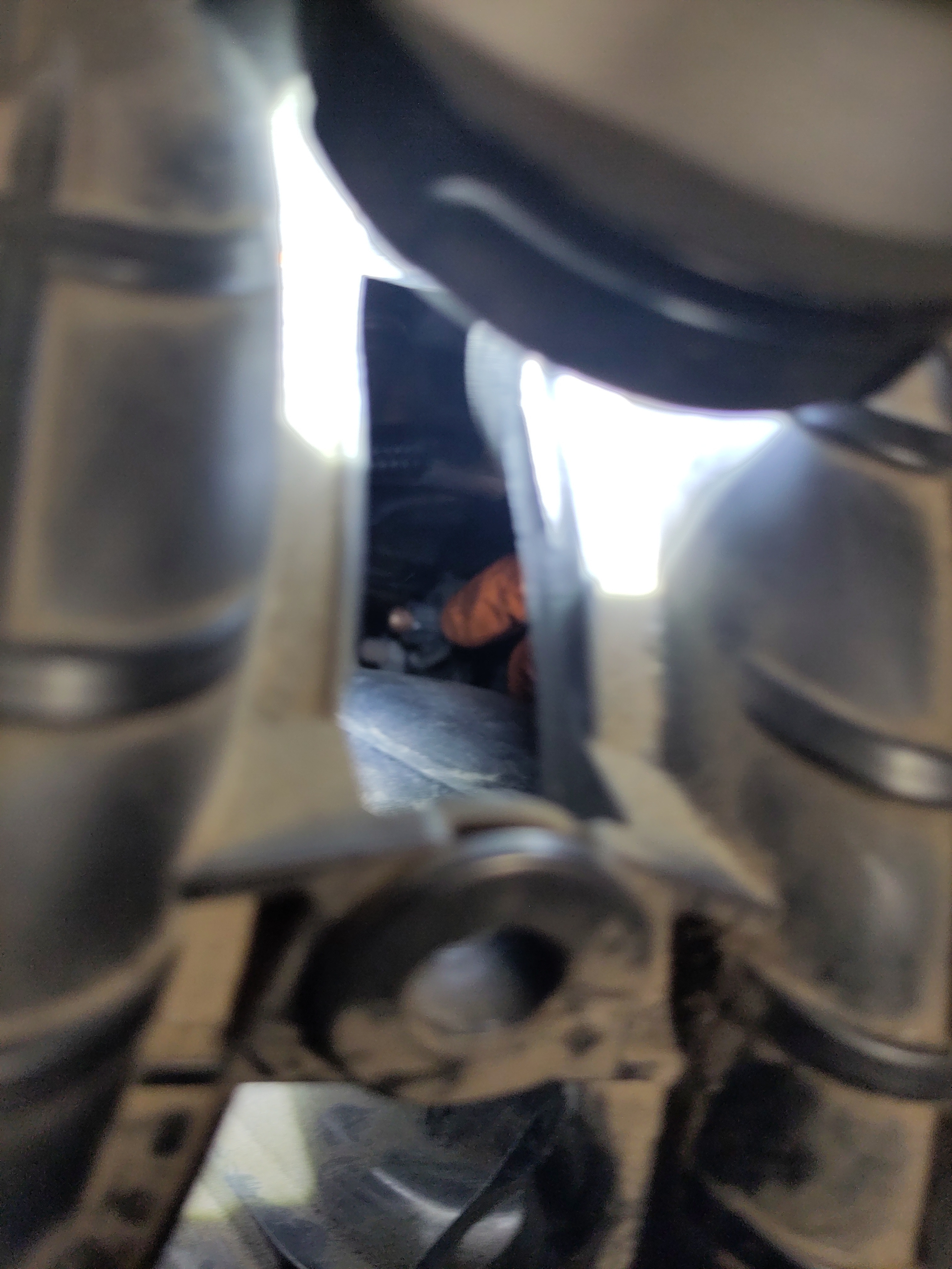
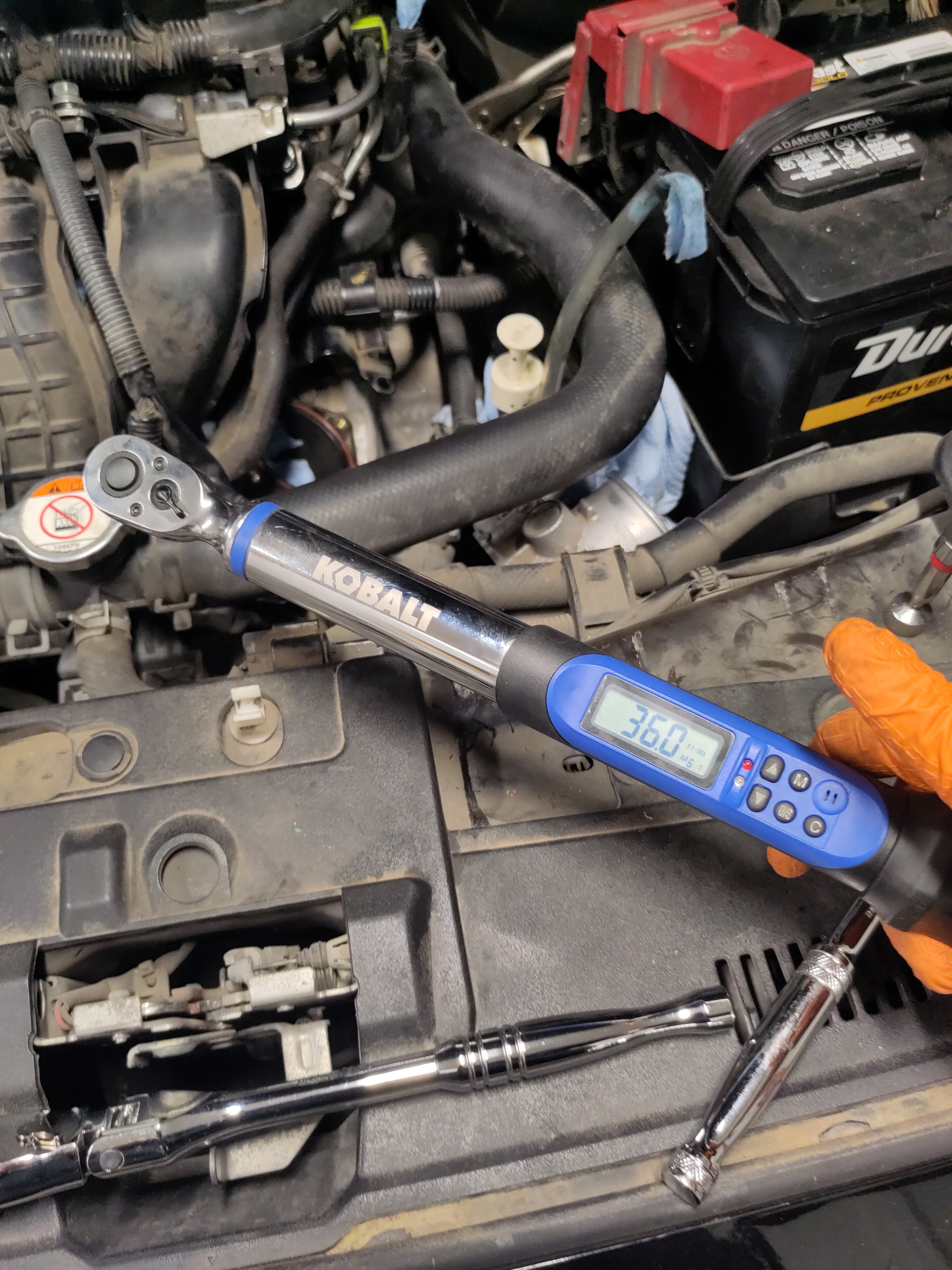
- Finish tightening the bolts to the starter by using the tools from the mentioned step 3 of the installation section of this tutorial. Once tightened use a 3/8" drive torque wrench and set it to 36 ft-lbs to torque those bolts to specifications. Note, the bottom bolt can be tricky, but getting the 14mm 6point deep socket should do the trick. The top bolt can be tightened with a 14mm 6 point shallow socket.
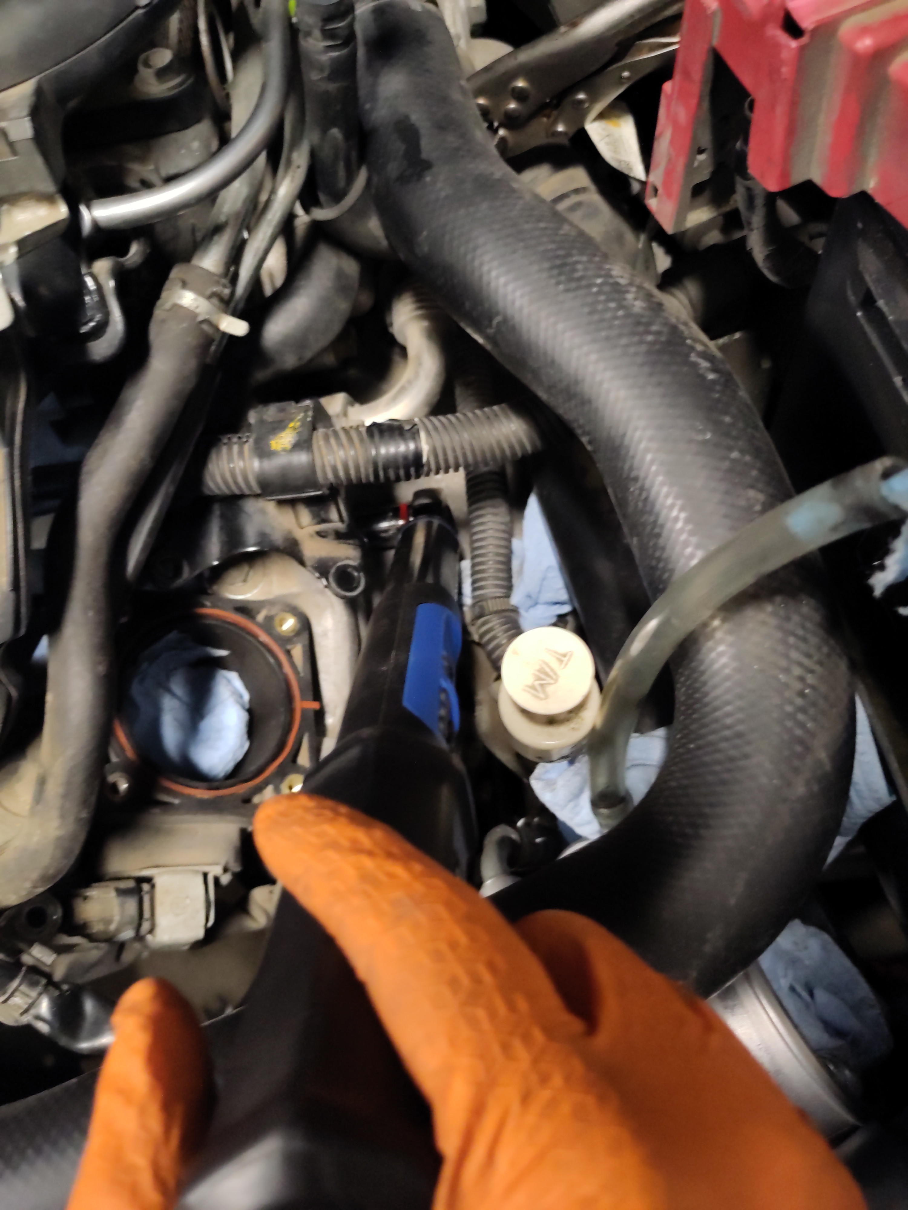
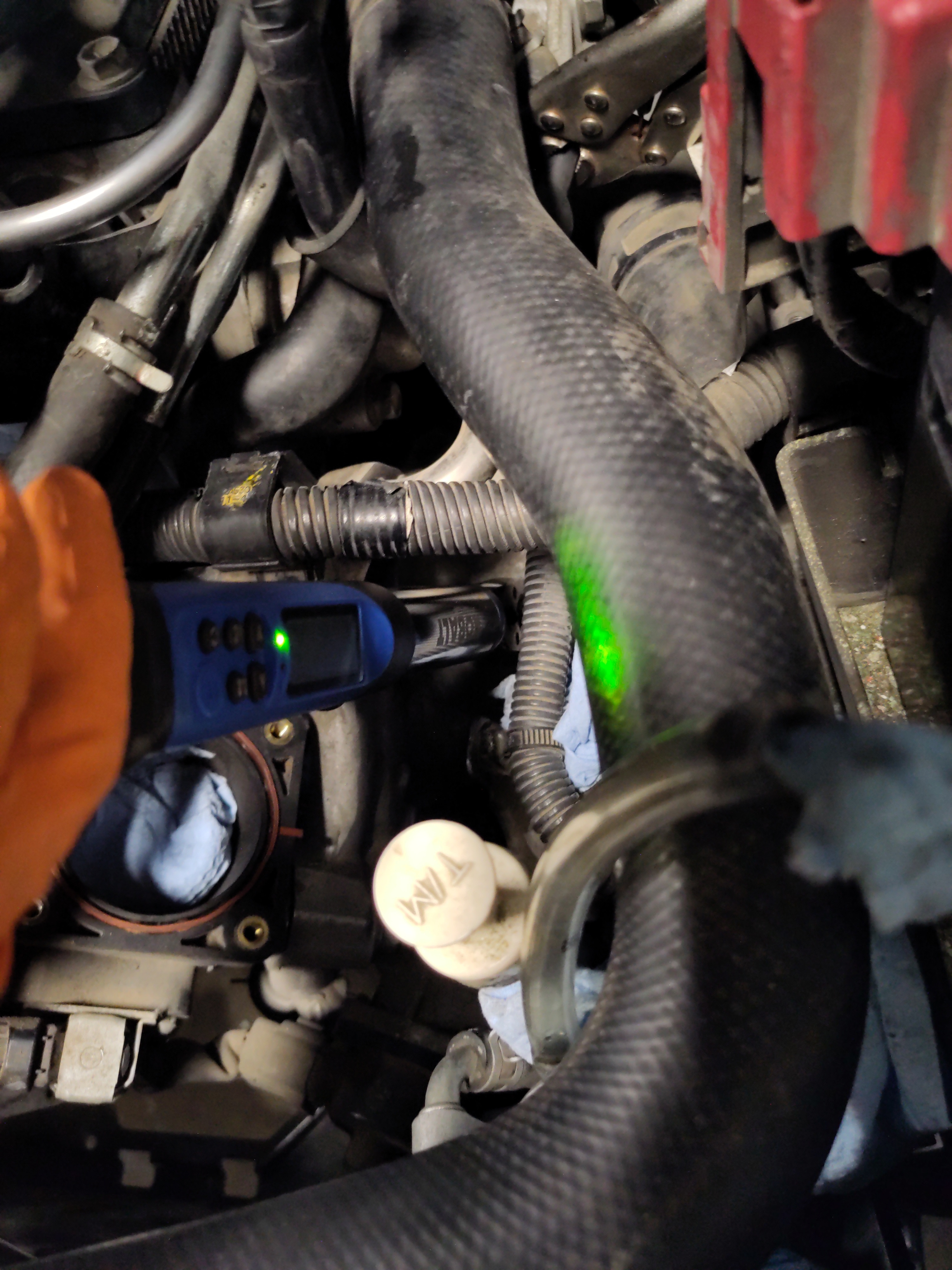
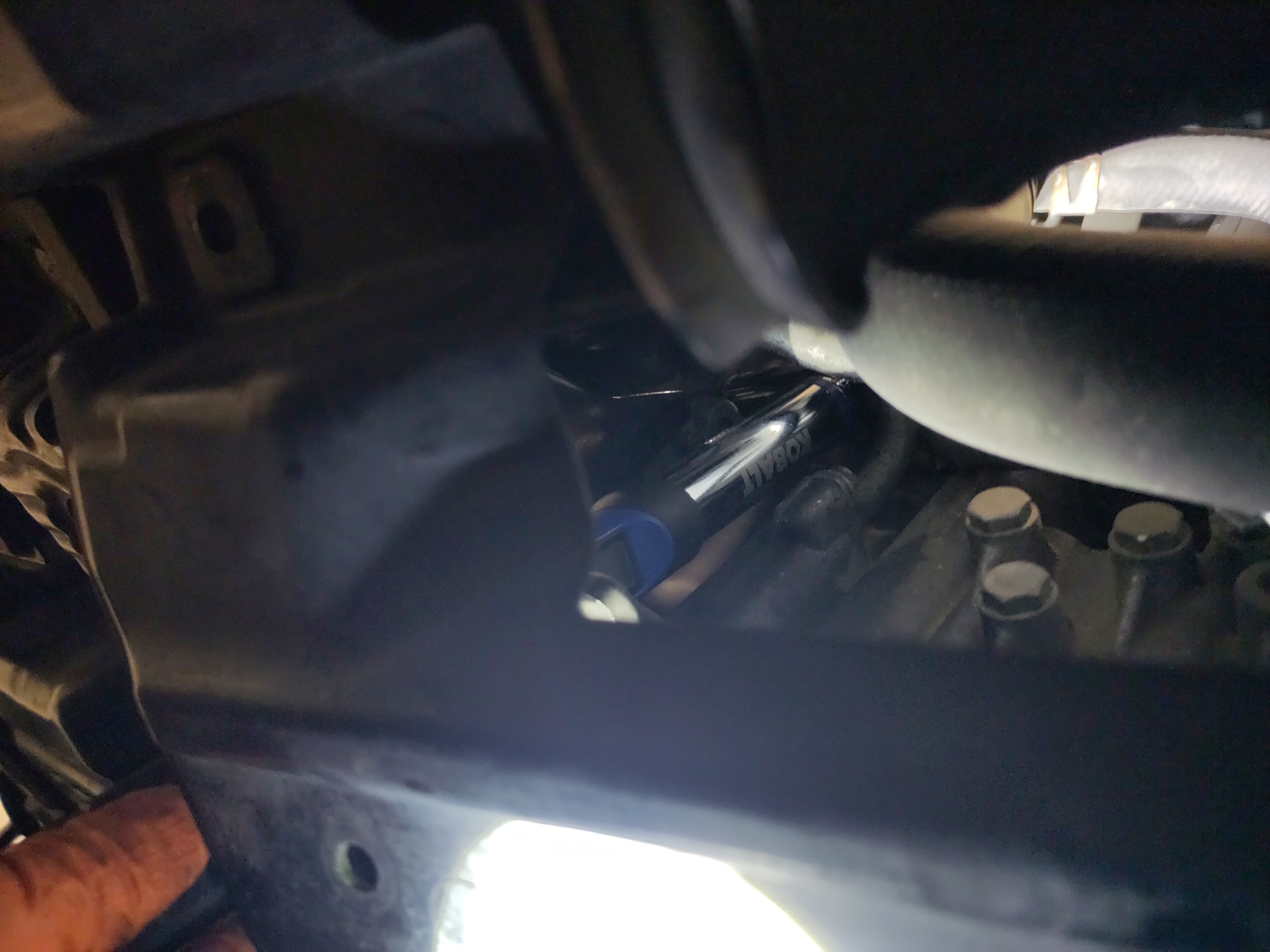
- It will be easier to re-attach the coolant hose back onto the throttle body before installing it and fastening it. Begin by removing the pieces of the paper towel from the hose ends. This step will have to be quick in order to prevent coolant to be spilled out. I would recommend using the nose pliers to stretch out the hole of the hose of a quick mounting. Ensure to layout clean dry paper towel to absorb spilled coolant. Now remove silicon hose and re-attach the hose onto the male end of the throttle body. Do not install the hose clamp that will happen in a later step just get female end attached to the male end.
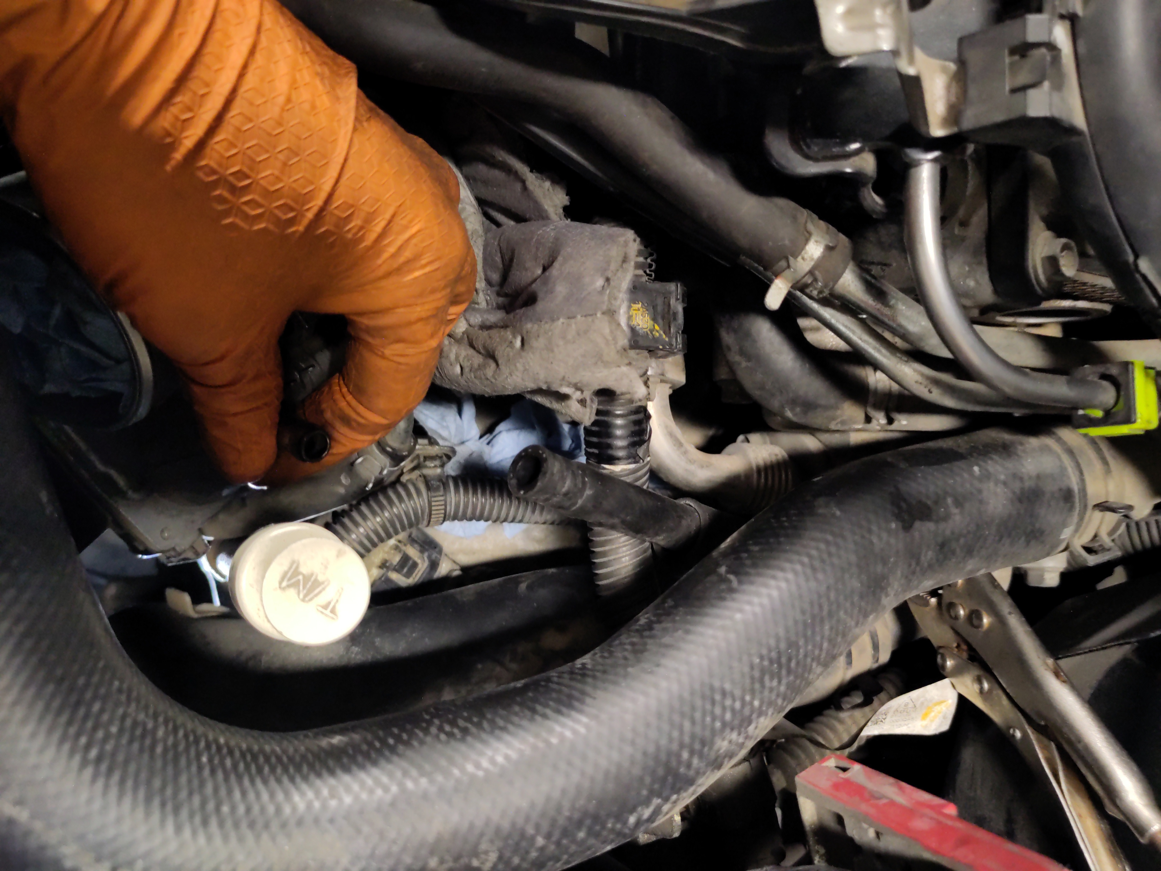
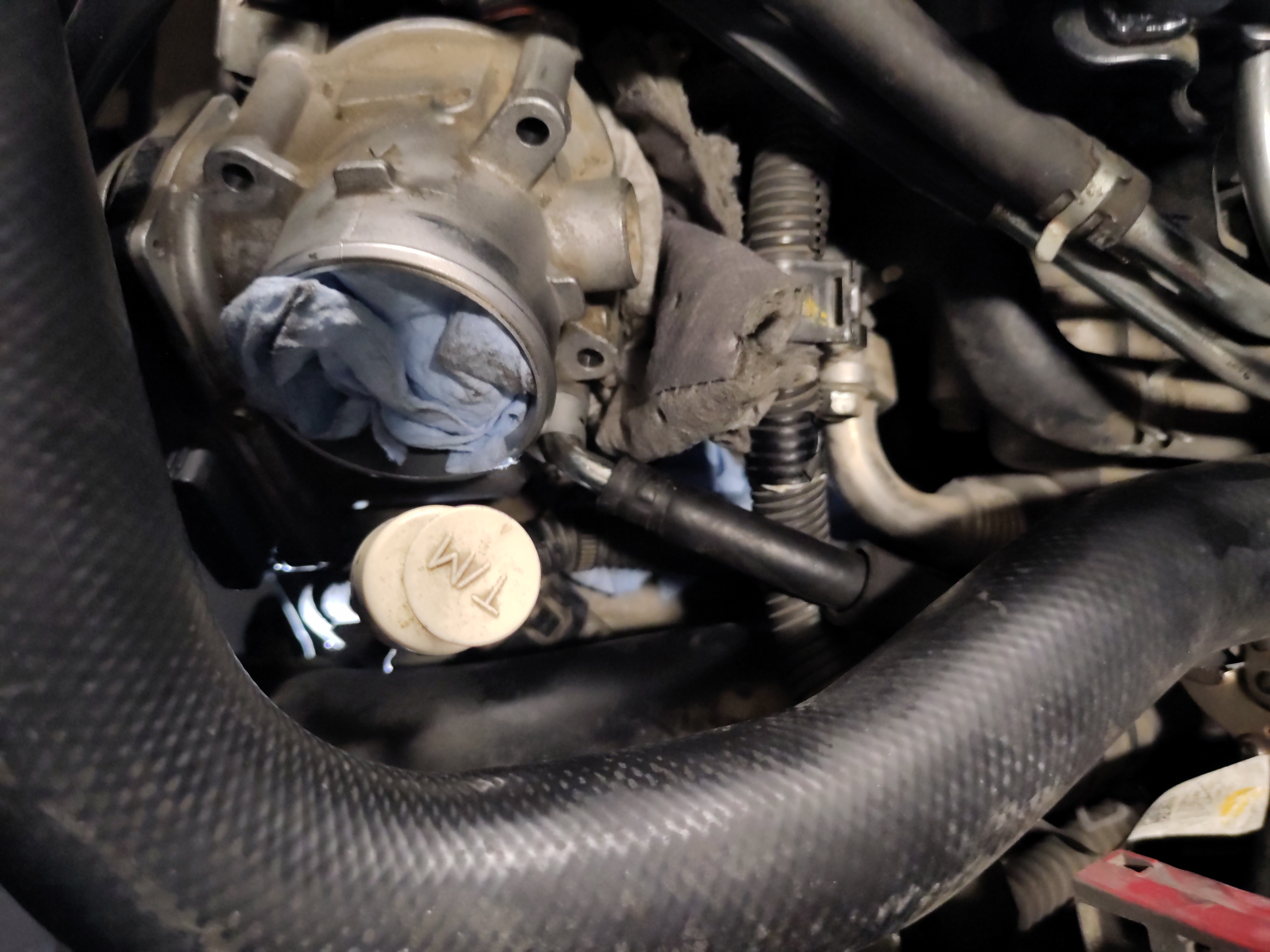
- Now it is time to reinstall the throttle body before installing, wipe down the surrounding area and remove the paper towel that was inserted into the hole. It a good idea to re-wipe down the entry way of the air intake.
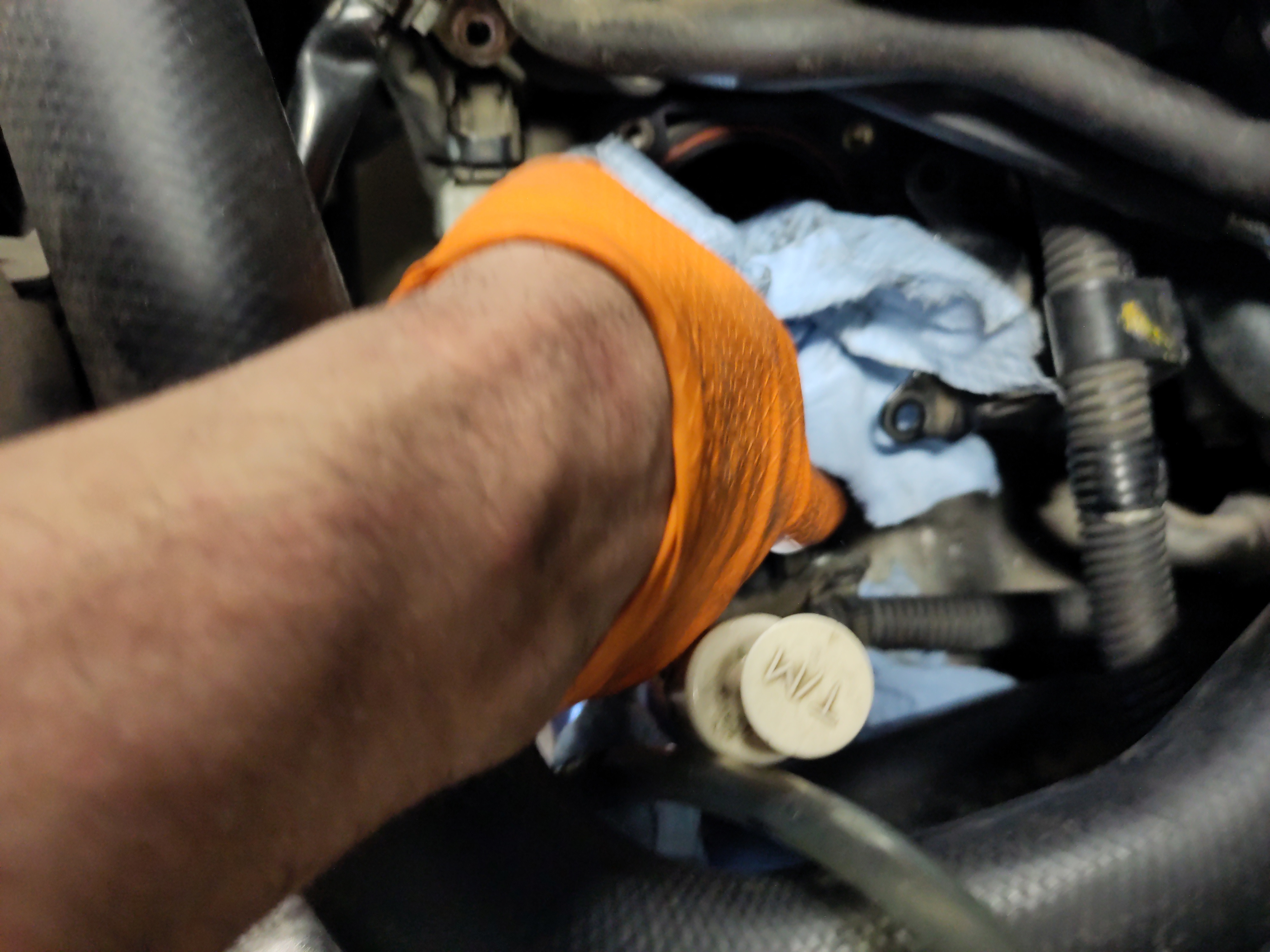
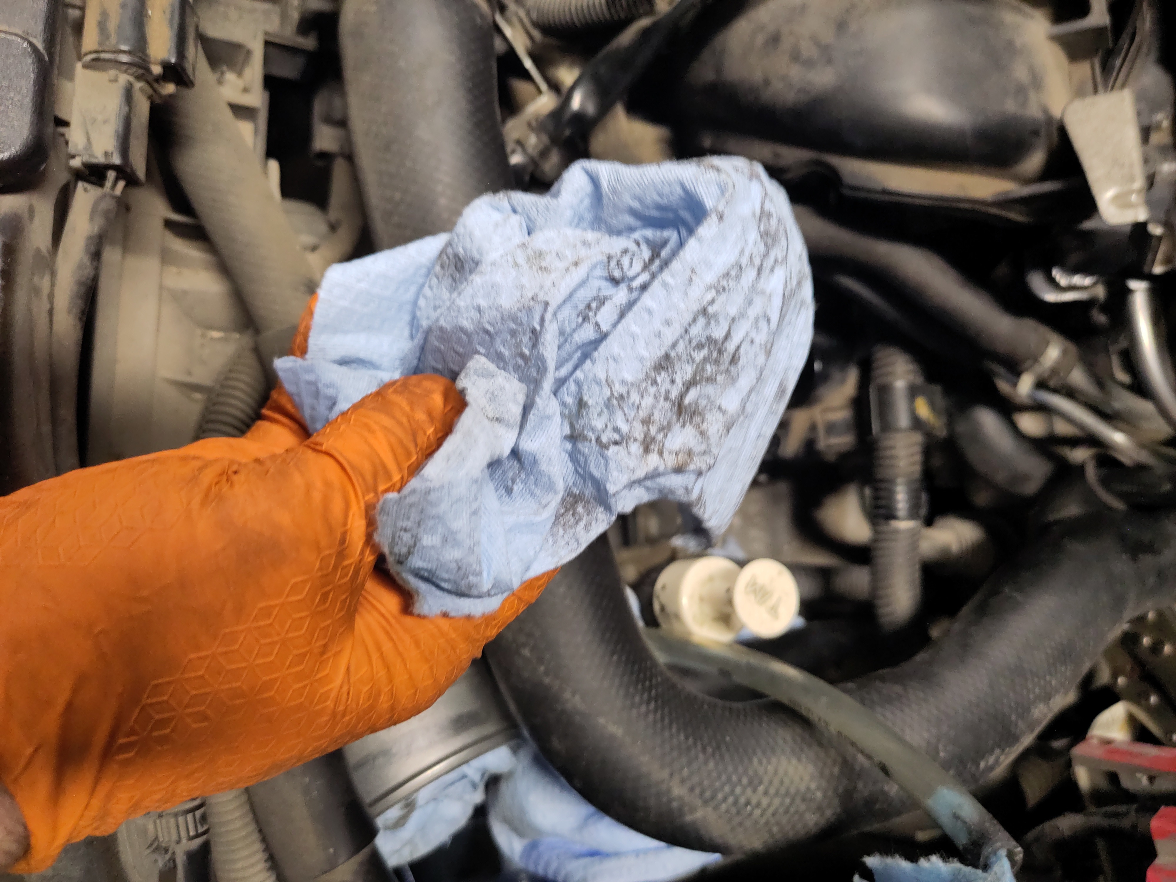
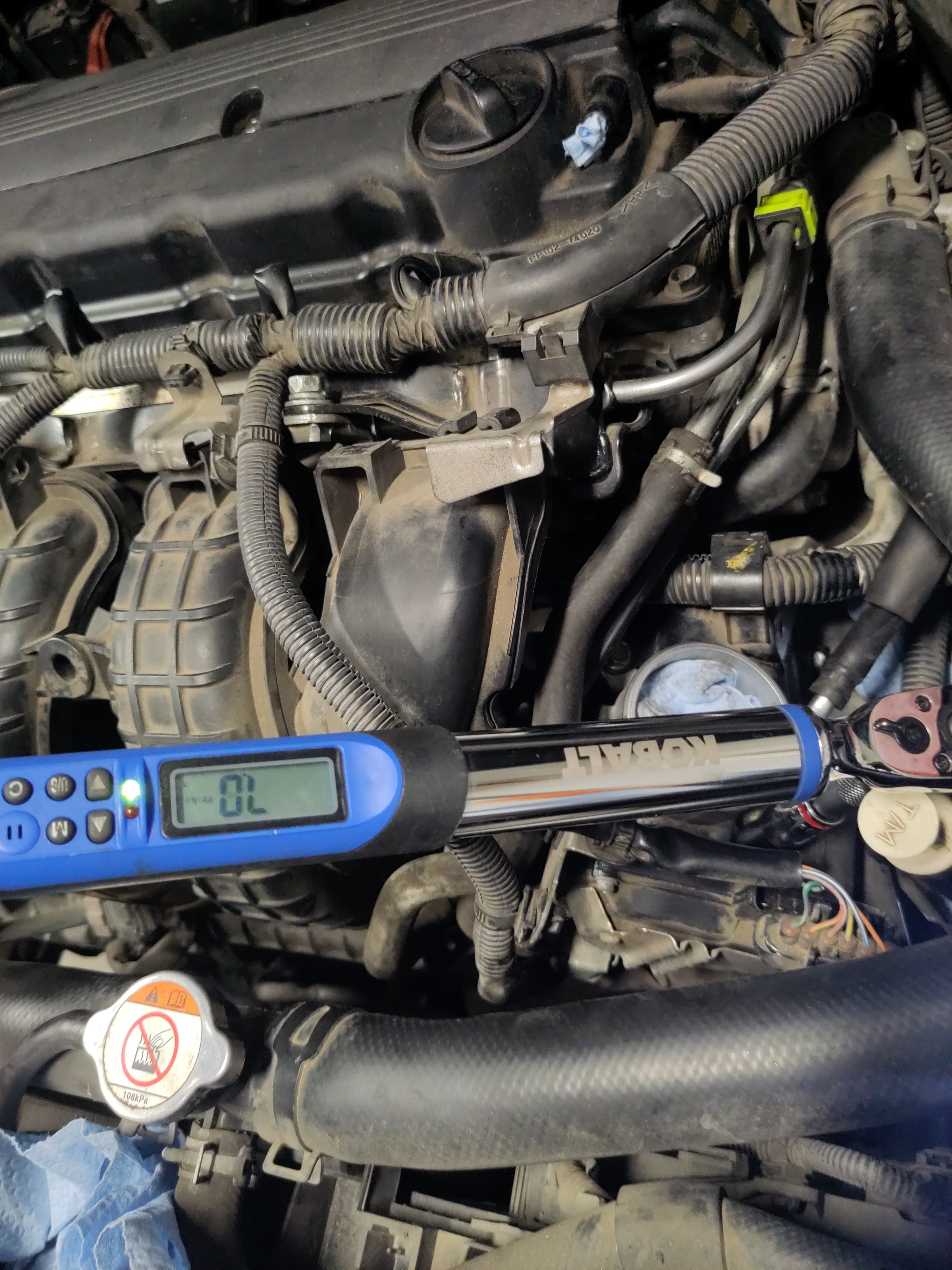
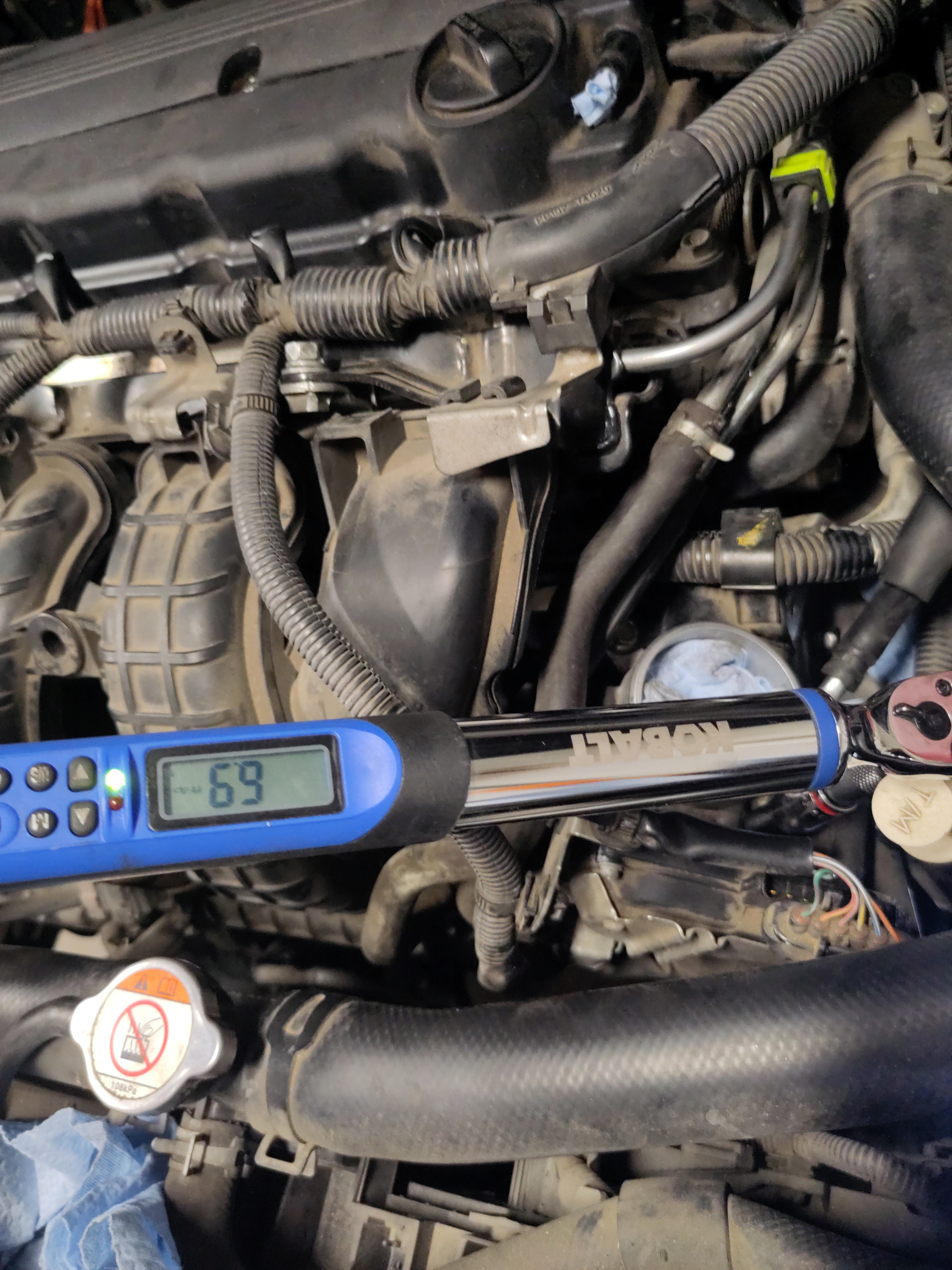
- Now place the throttle body in its original position and using the 4x 10mm bolts hand thread them so in order to align the threaded holes. It is important to not just secure one bolt at a time but secure them evening so there is a good seal. As in, secure the bolts diagonally, but evenly. Using a 3/8" drive 10mm shallow socket with an extension will be adequate to hand thread the bolts down following using a 3/8" power tool socket wrench. Finally, torque the bolts using the 3/8" drive torque wrench. The torque specs for the bolts is 7 ft-lbs and the set torque wrench to the specification and begin to secure them. Make sure to line up the electrical hangers to the bolts as well.
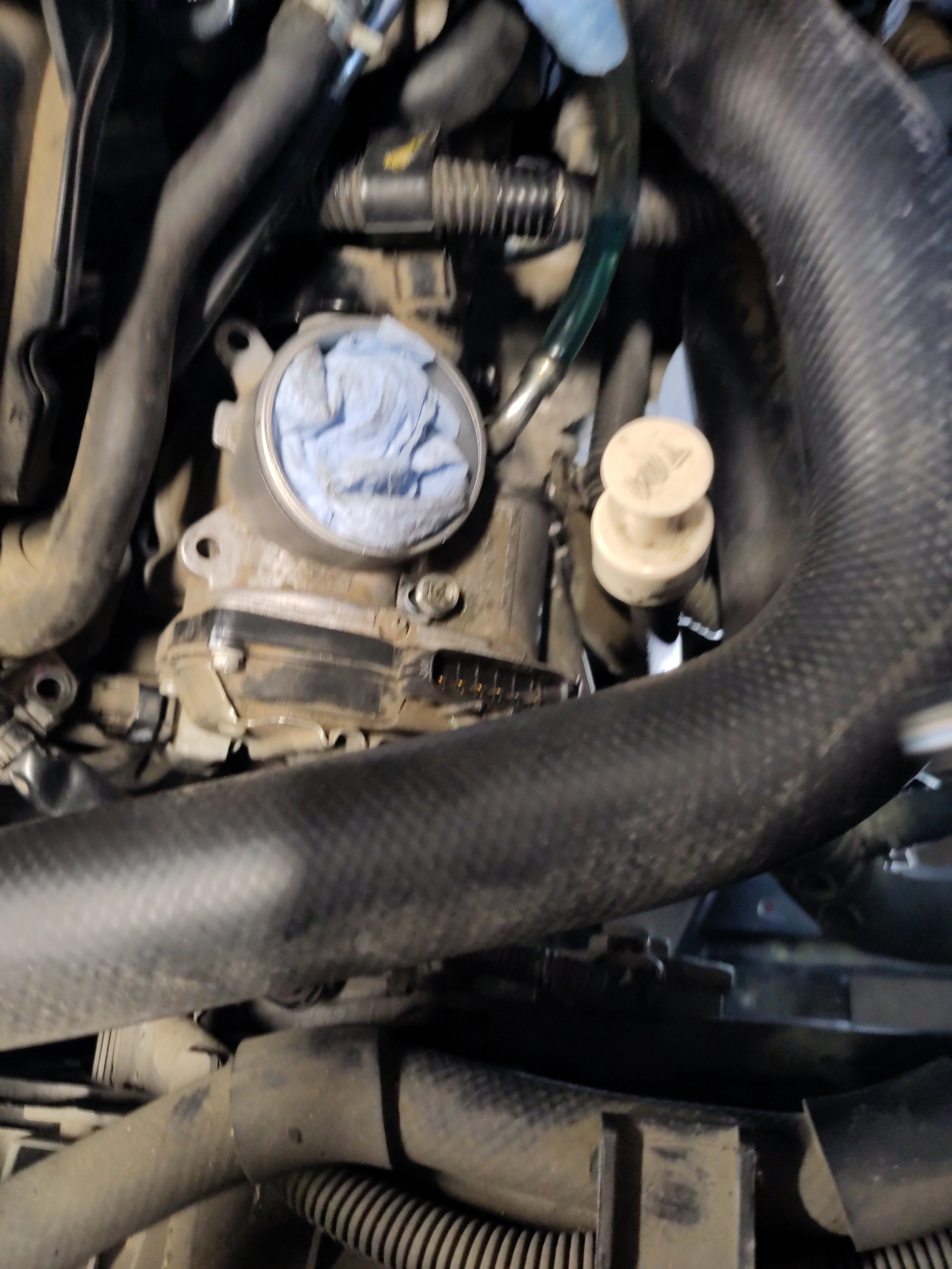
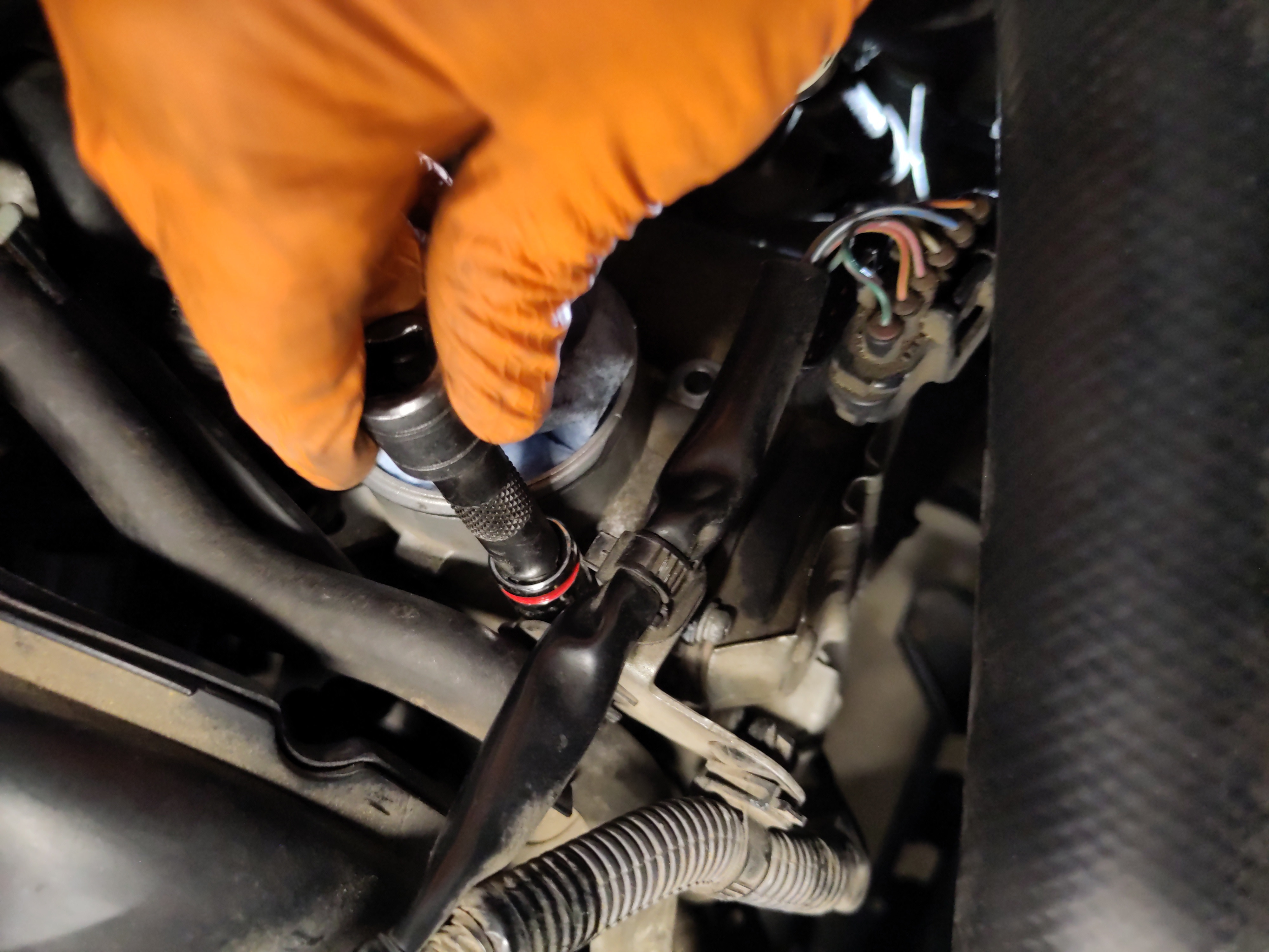
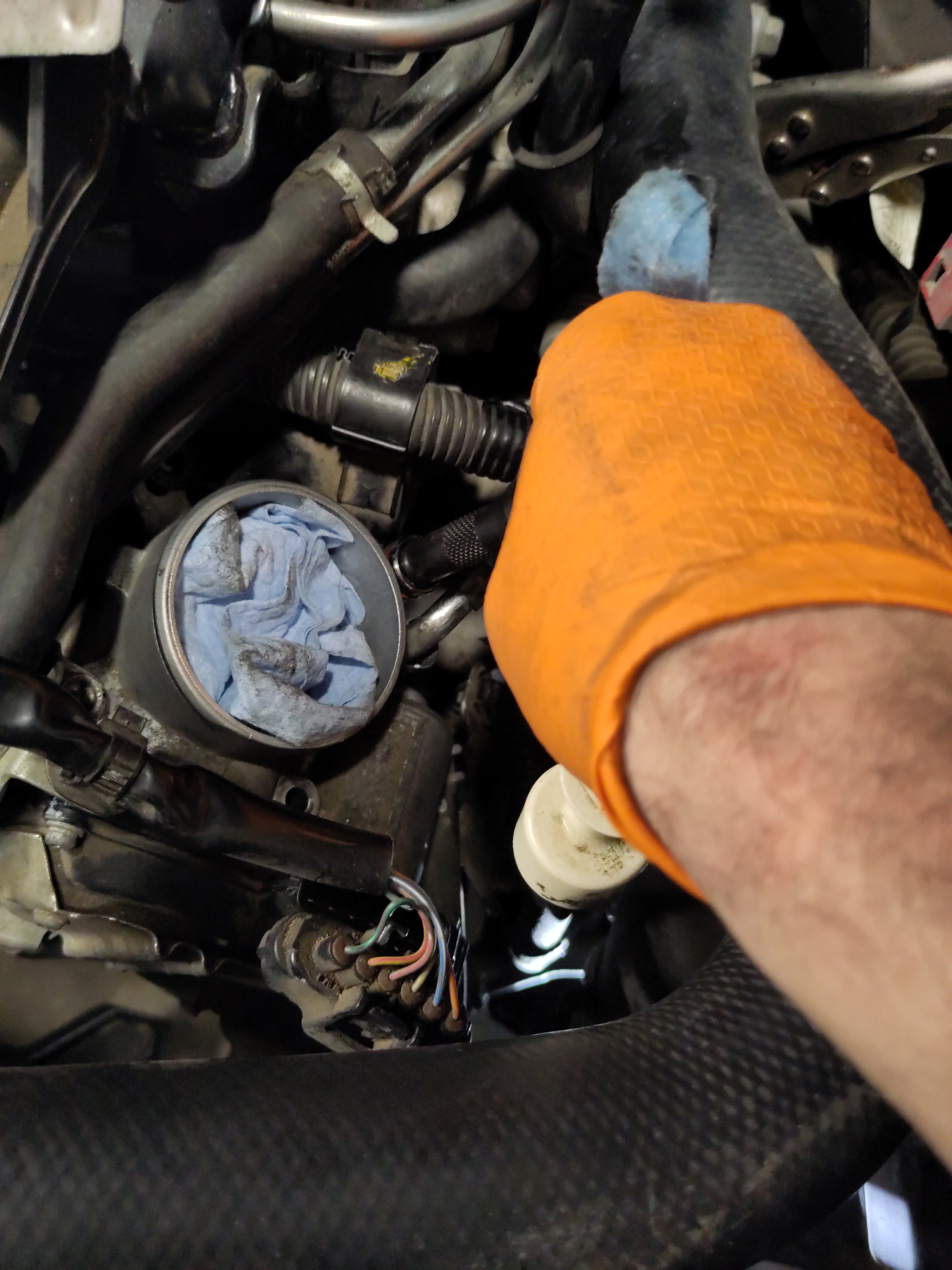
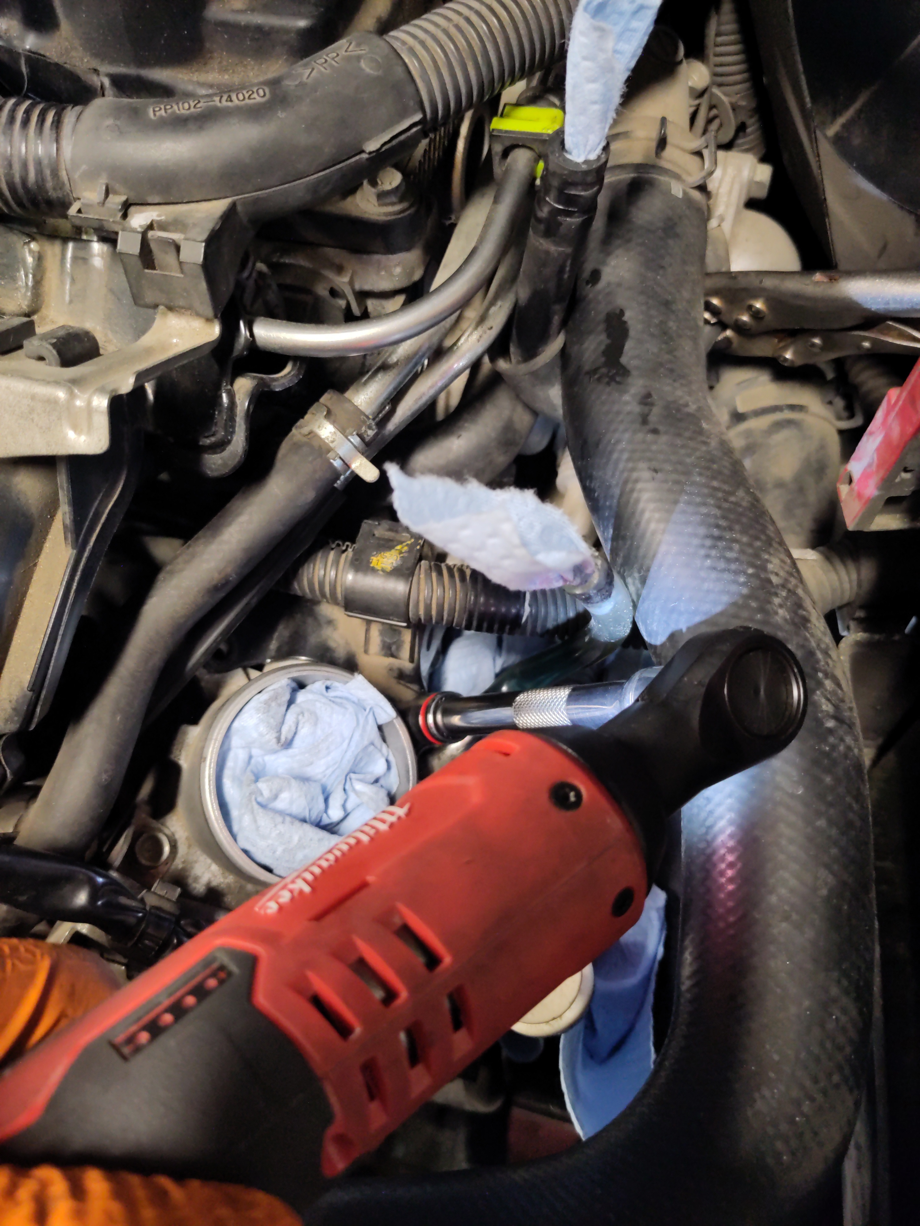
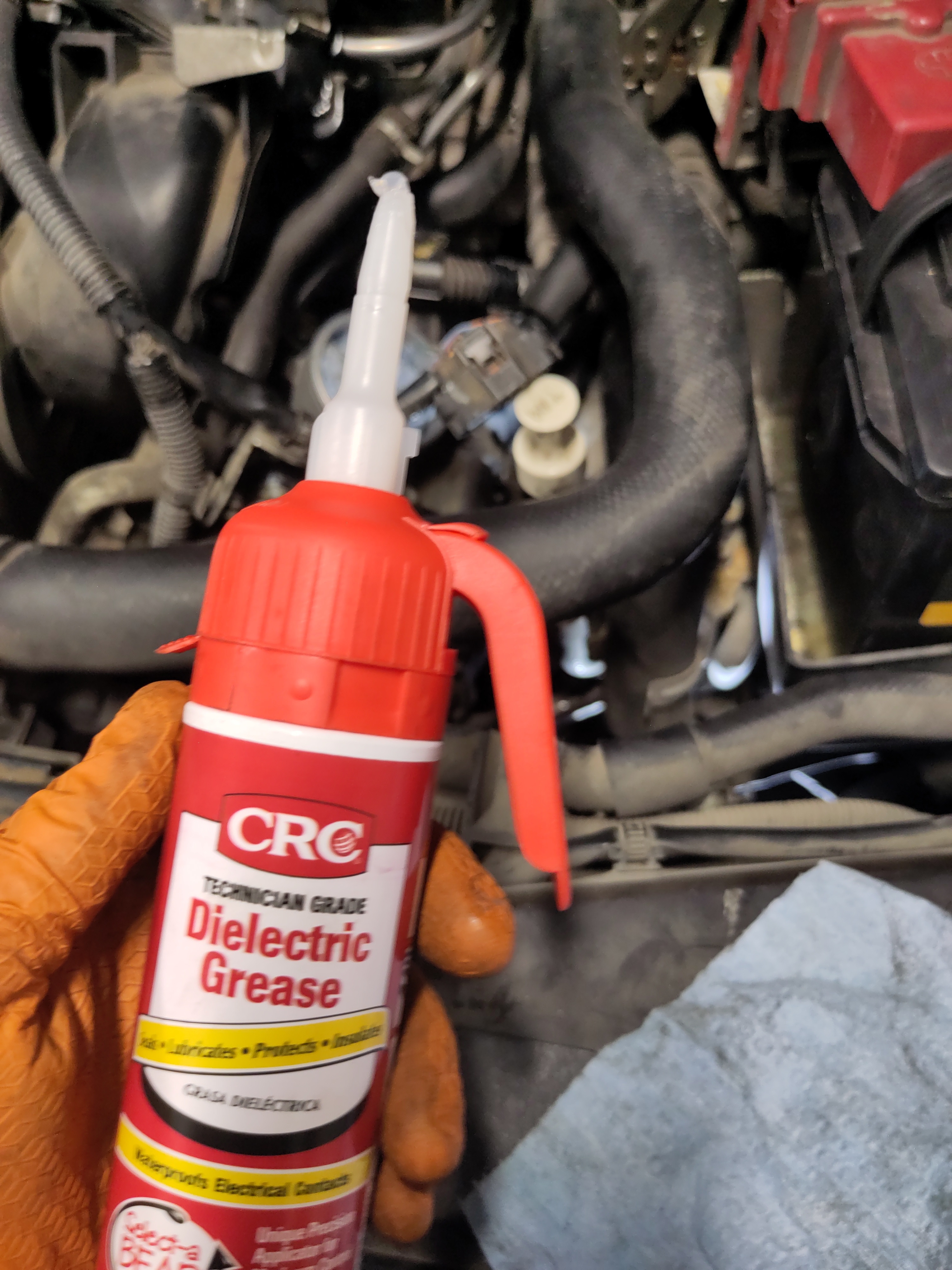
- Before connecting the electrical connection to the throttle body is would be recommended to use a q-tip and dielectric grease and apply it to the pins to ensure there secure connection and no corrosion build up occurs over time. Then reconnect the wiring harness to the connection. There should be an audible click to confirm a secure connection.
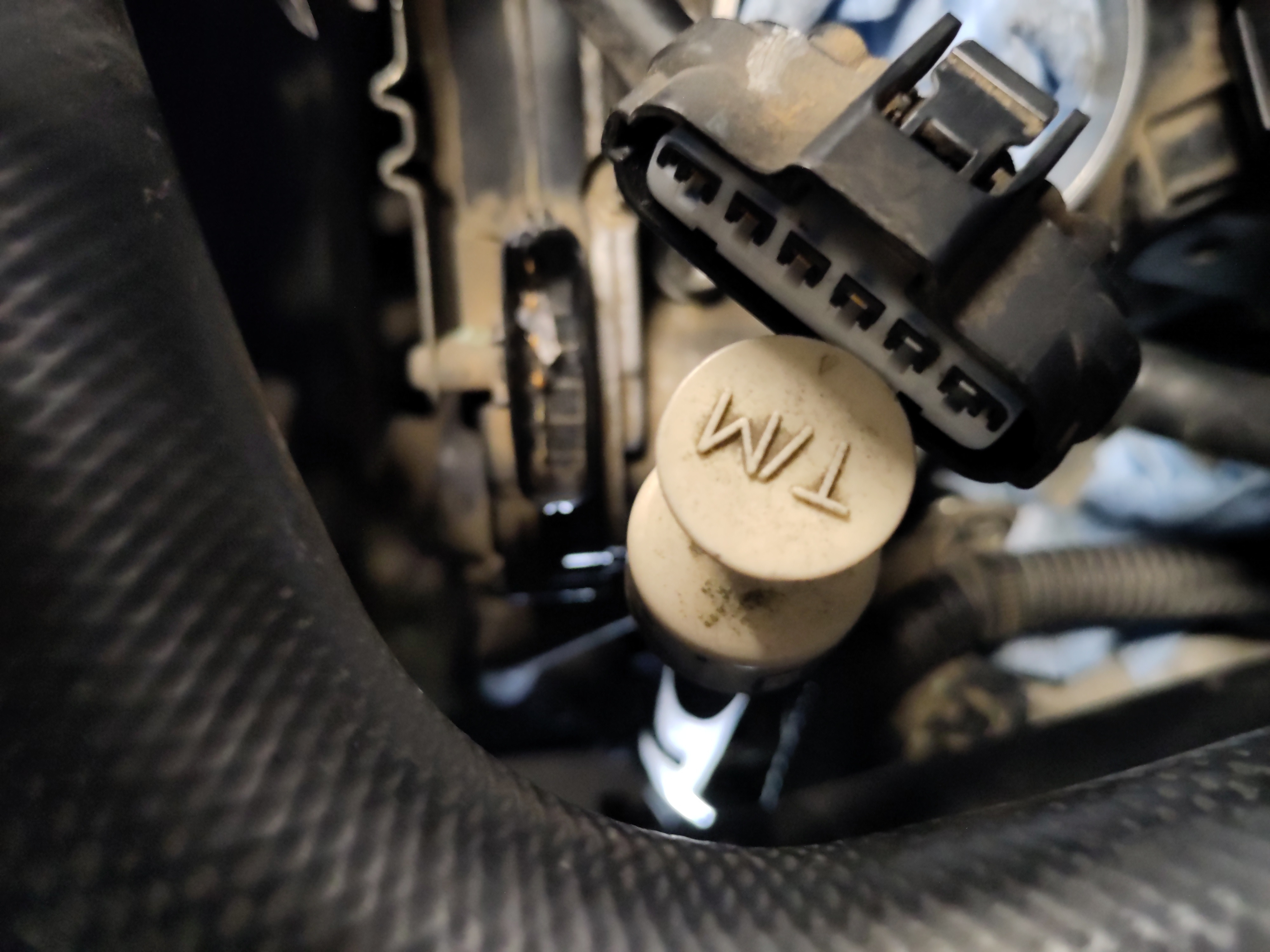
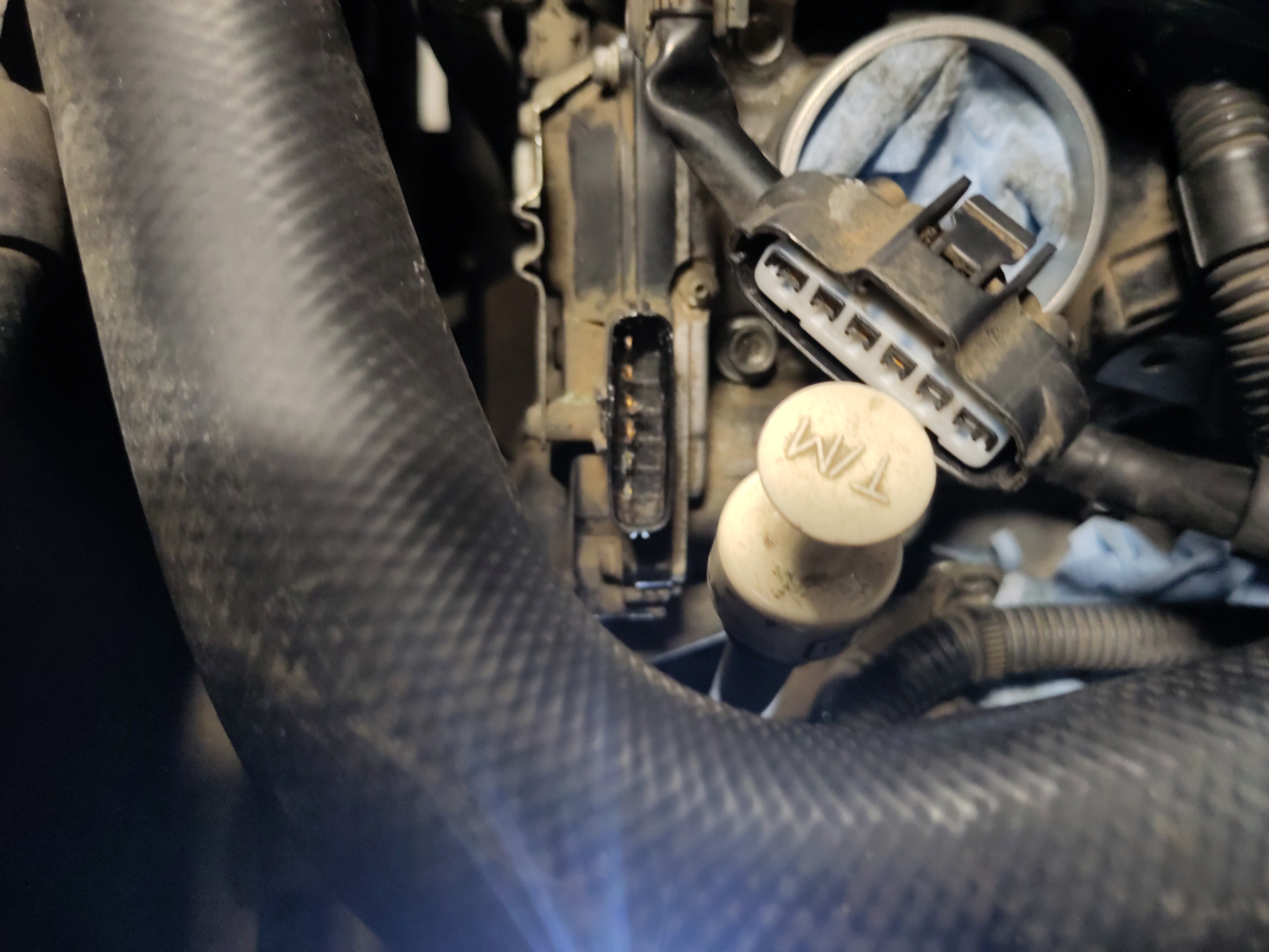
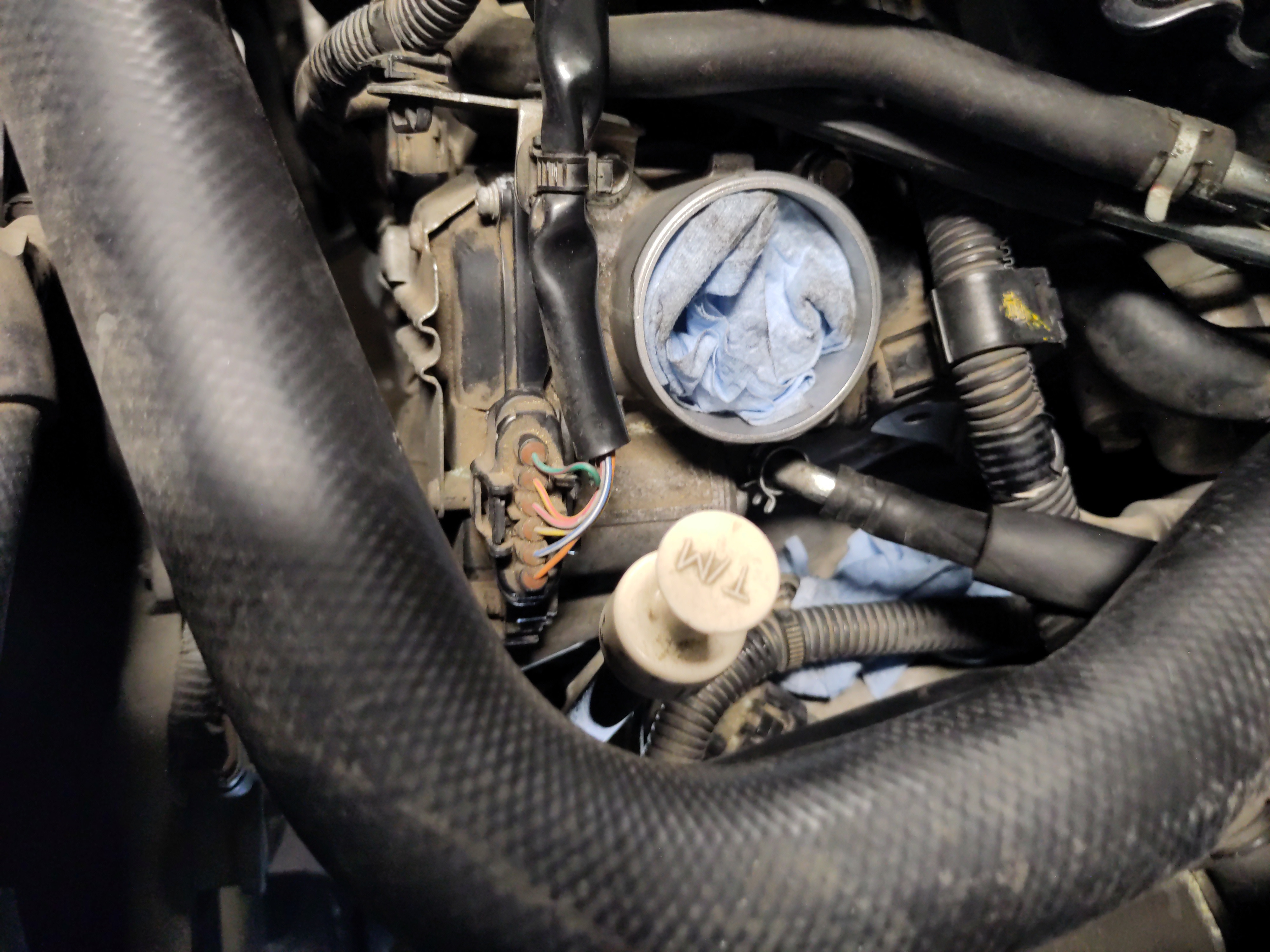
- Using the long reach bent needle nose pliers to secure the hose clamp back onto the throttle body coolant hose. Try to position the hose clamp into the original position of the indentations.
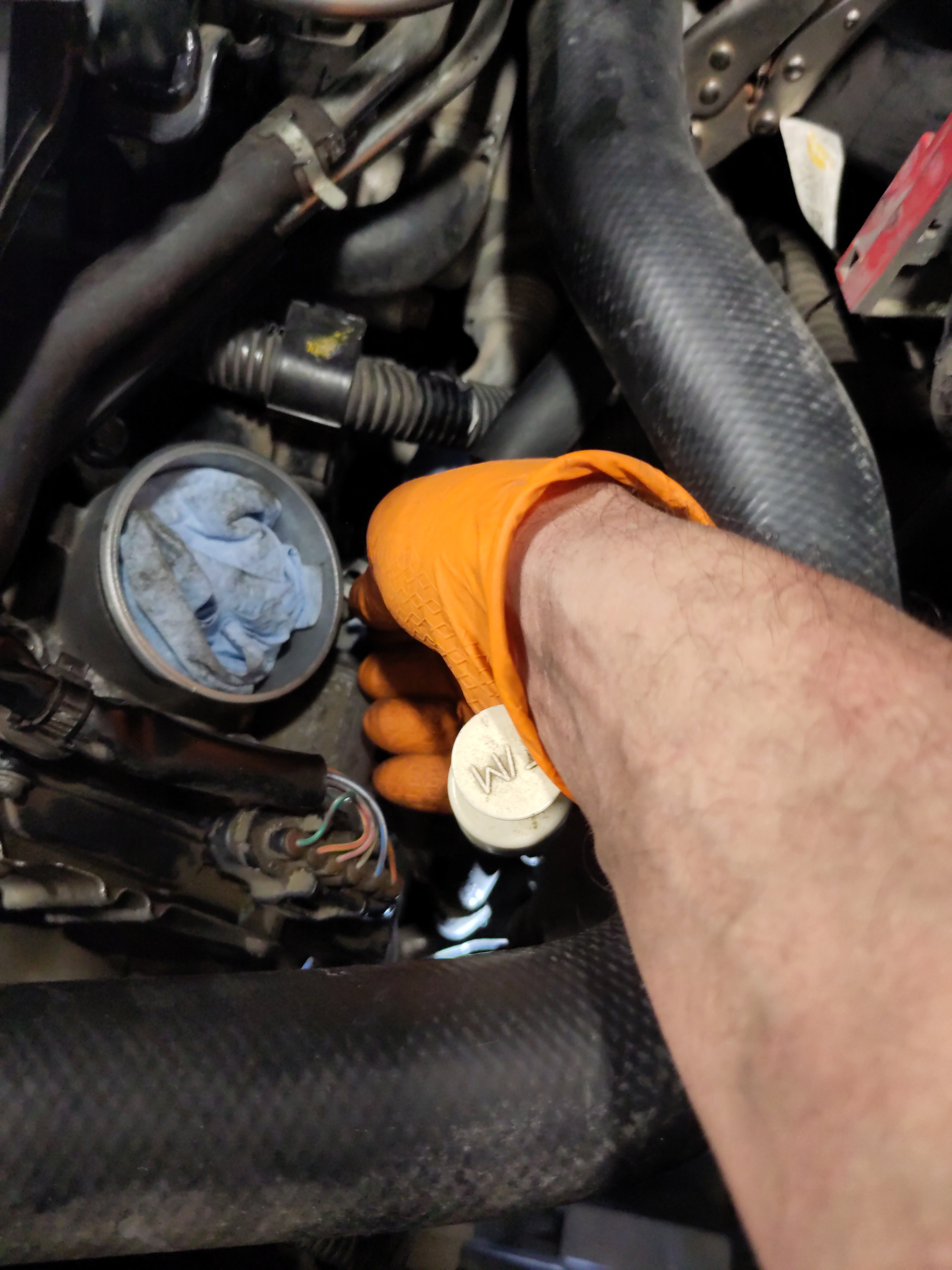
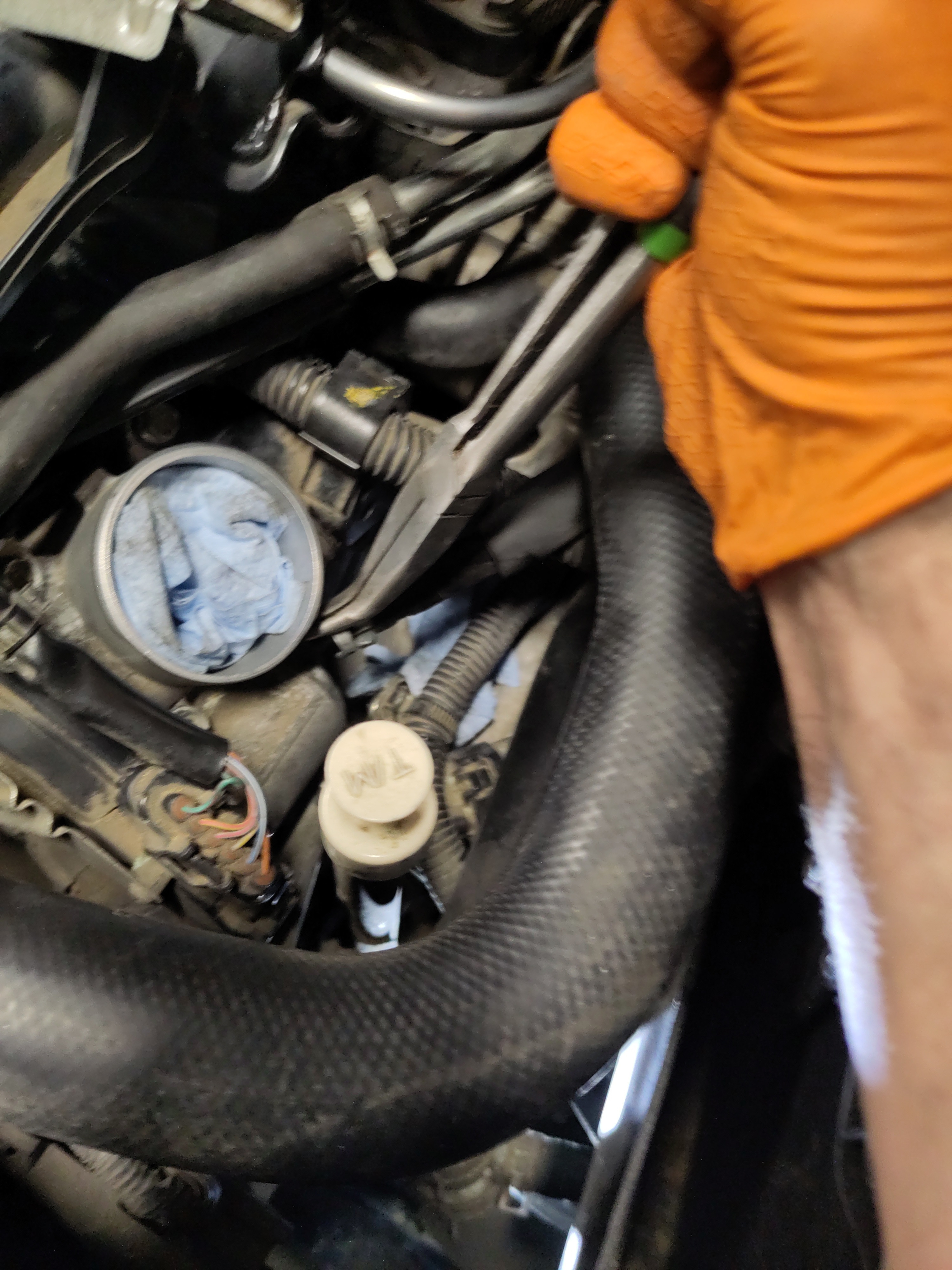
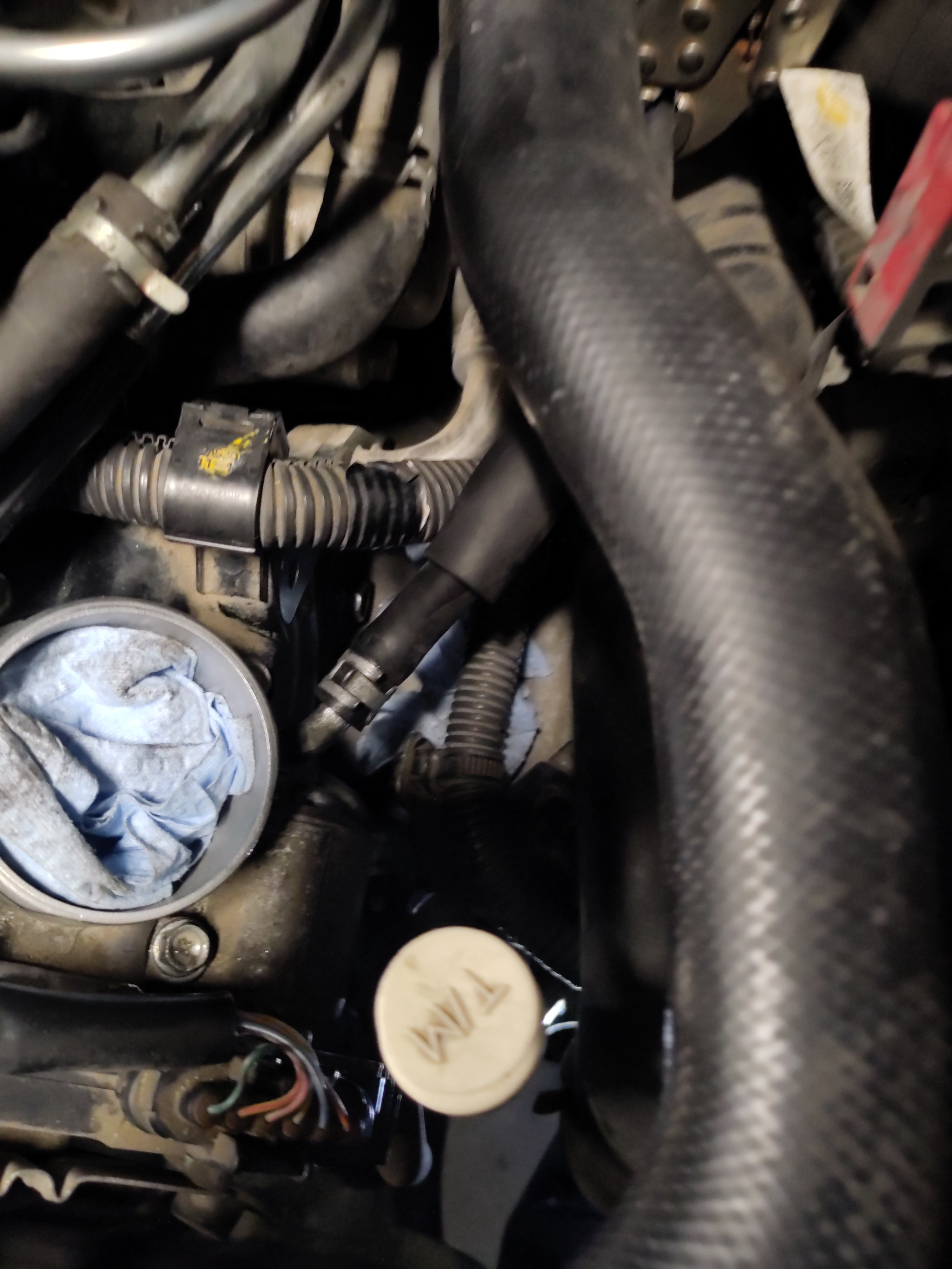
- Remove the curved jaw locking pliers from the upstream coolant hose.
- Now there is a support bracket for the air intake that needs to be hand threaded into the threaded hole underneath the vacuum hose. See pictures below. The bolt is 10mm bolt and just needs to be threaded in by hand. The bolt will be torqued down in a later step.
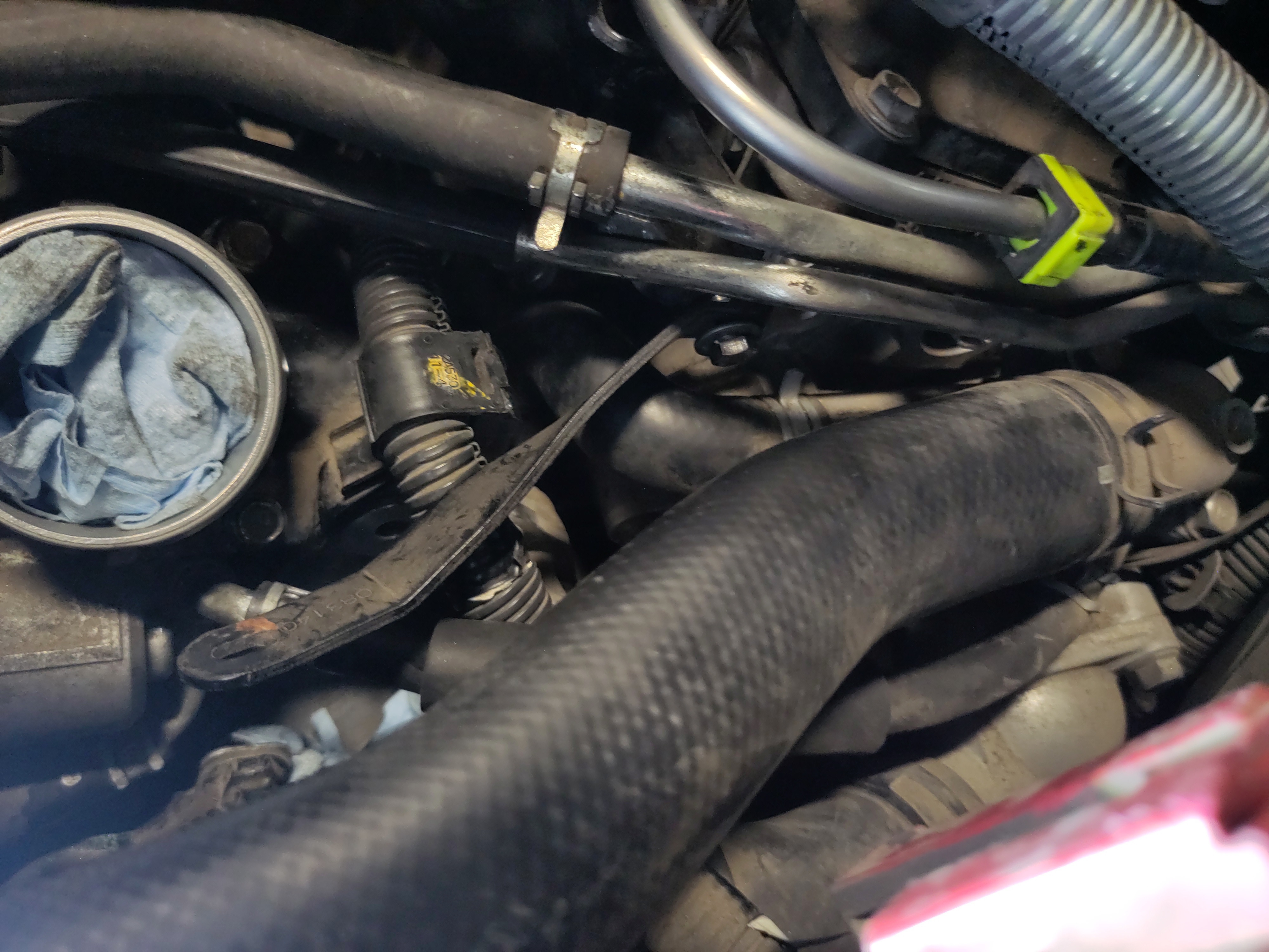
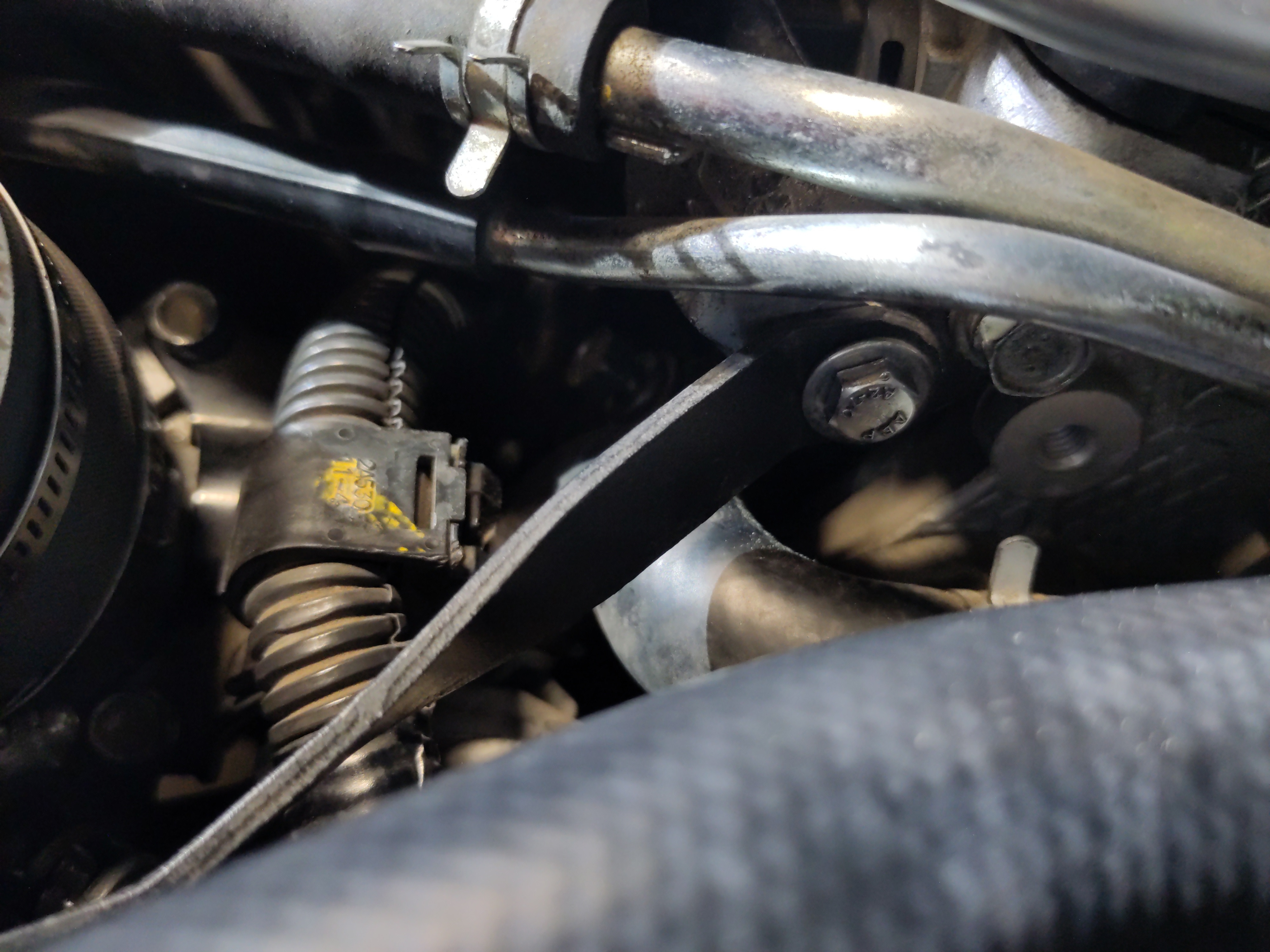
- Take the hose and mount it on to the throttle body and line up the hose clamp to where the screw can be easily accessed with a flat head. Make sure the hose clamp is around the hose and the male end of the throttle bottle. Tighten down the hose clamp.
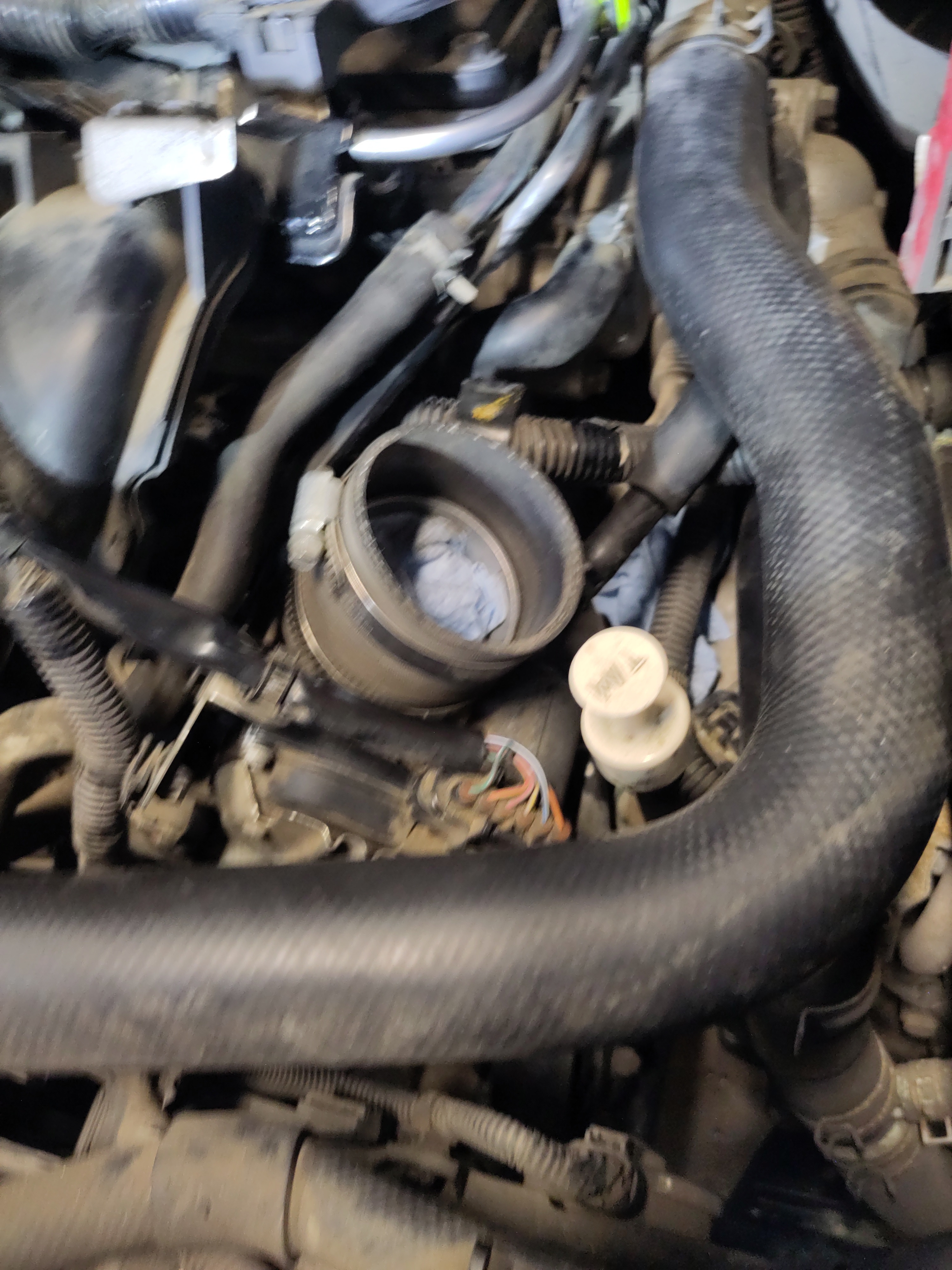
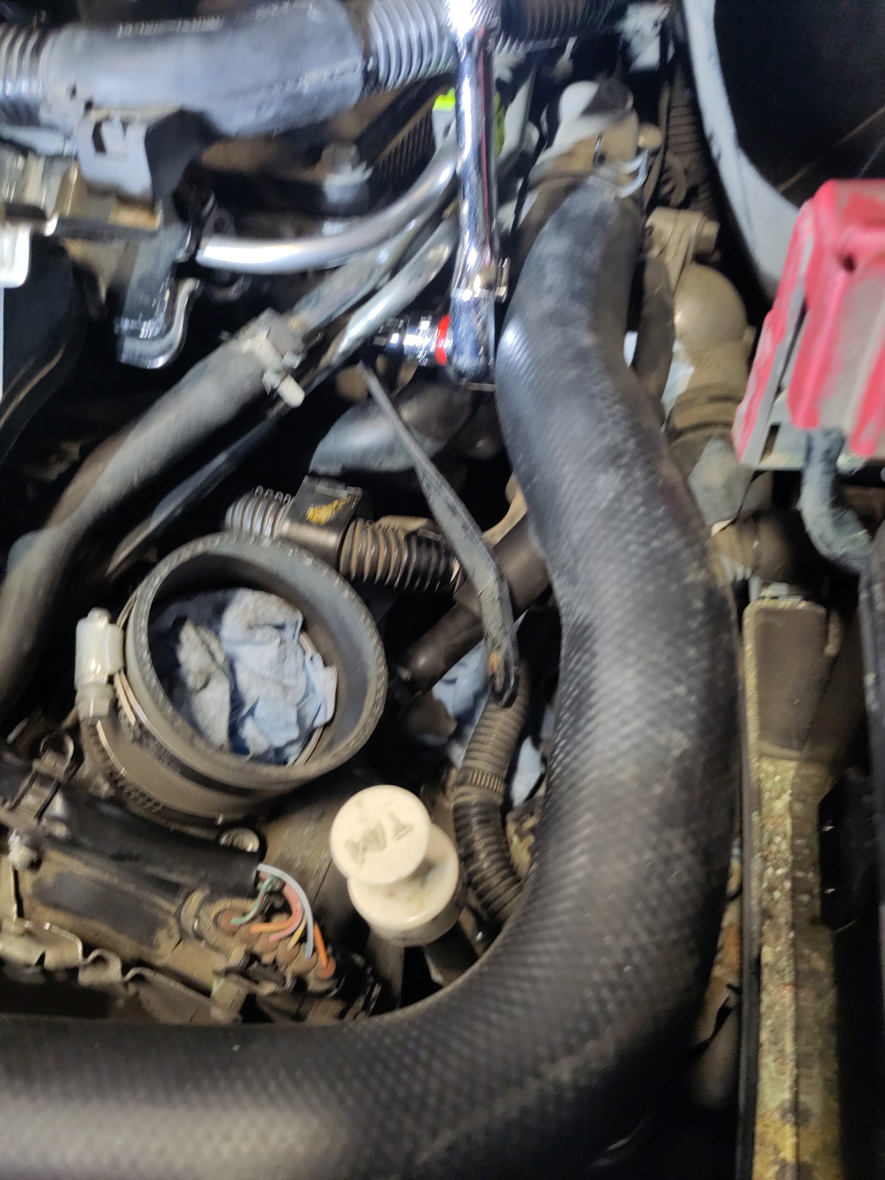
- Be sure to remove the paper towel from the throttle body entry point. Install the air intake pipe into the hose and push the intake pipe the hose. Do not tight the hose clamp yet. It will be done in a later step.
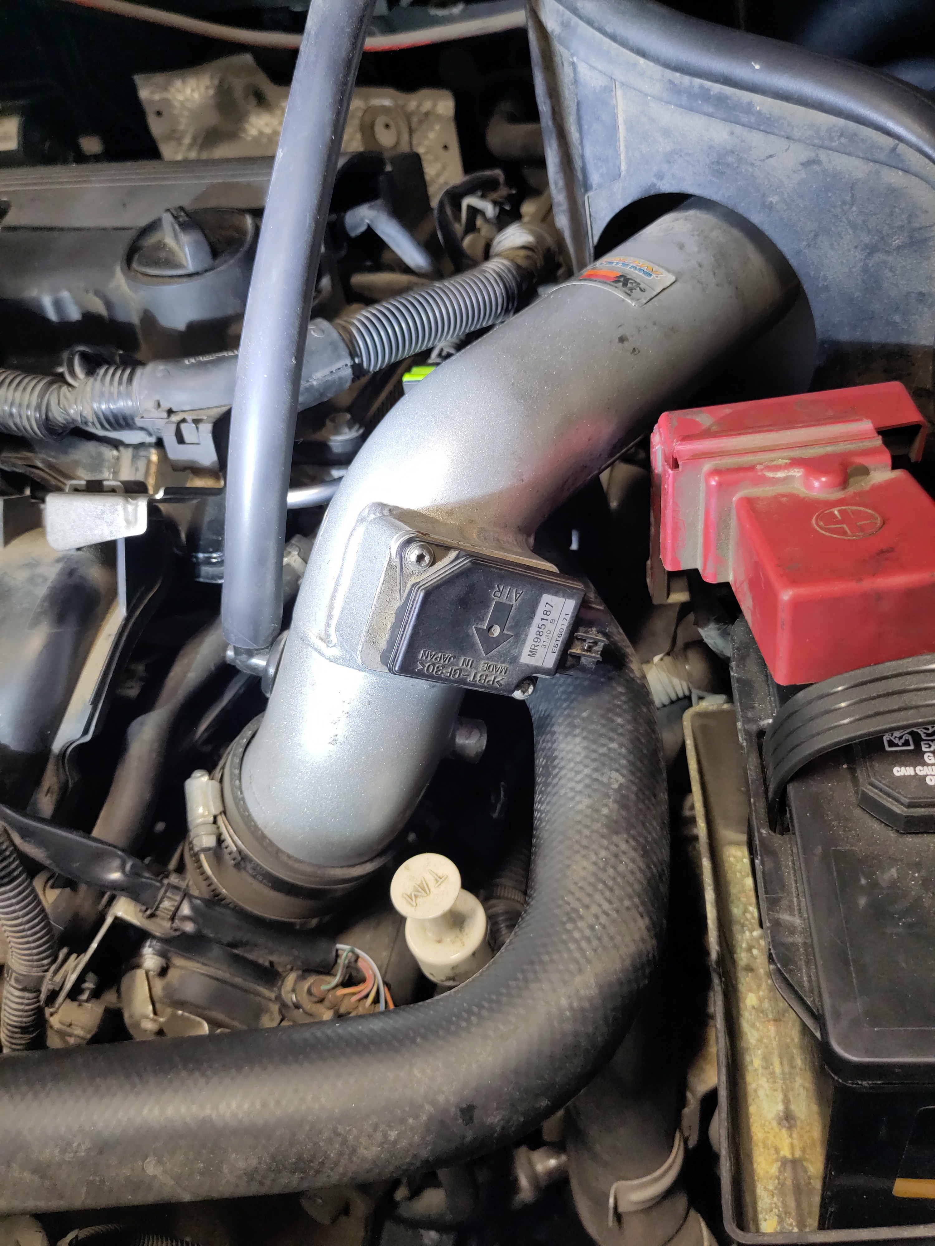
- Pull out the piece of paper towel inserted into the vacuum hose and connect the hose connected to the intake pipe to the male end near the oil cap. See photos below for a visual aid.
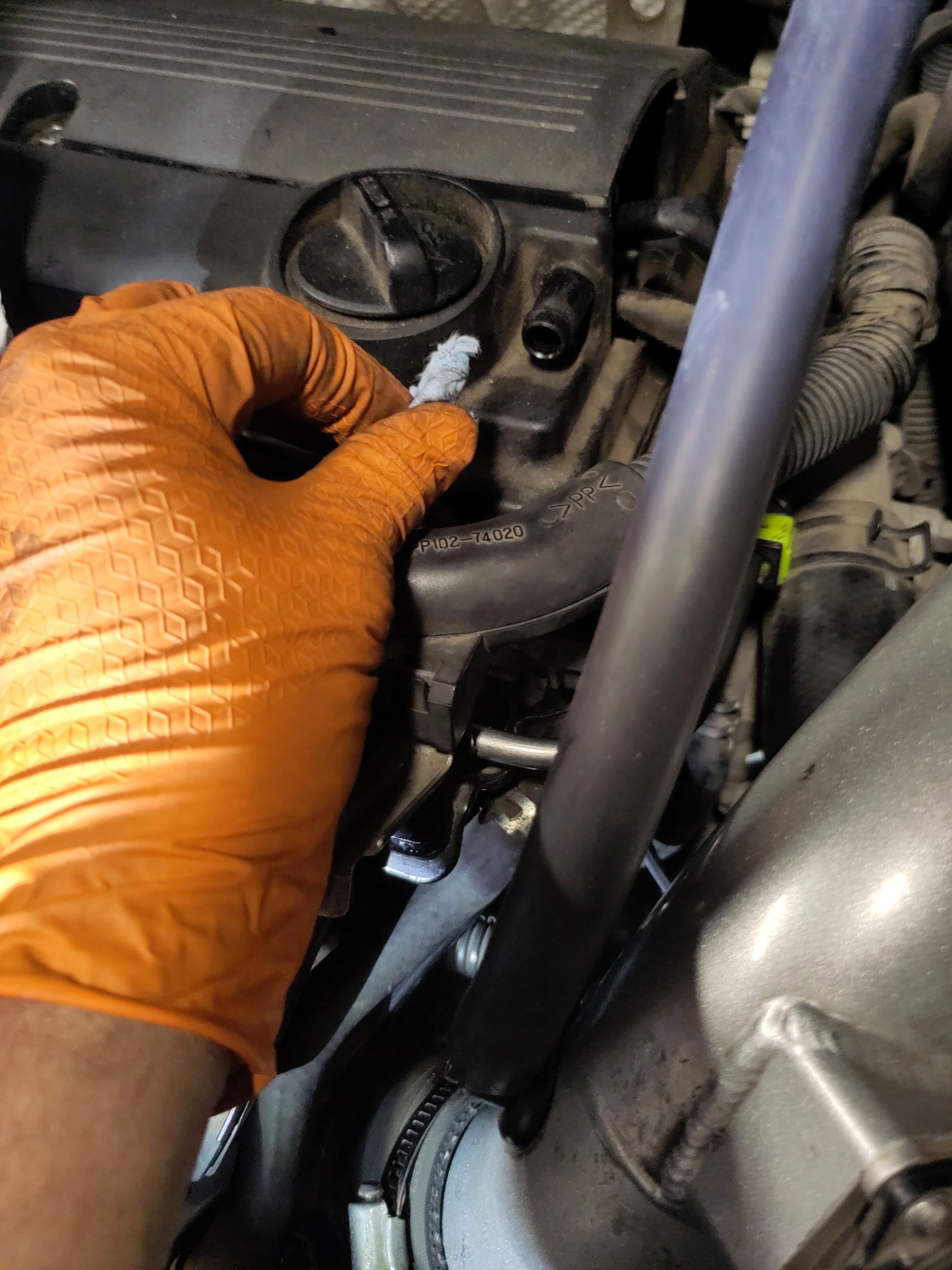
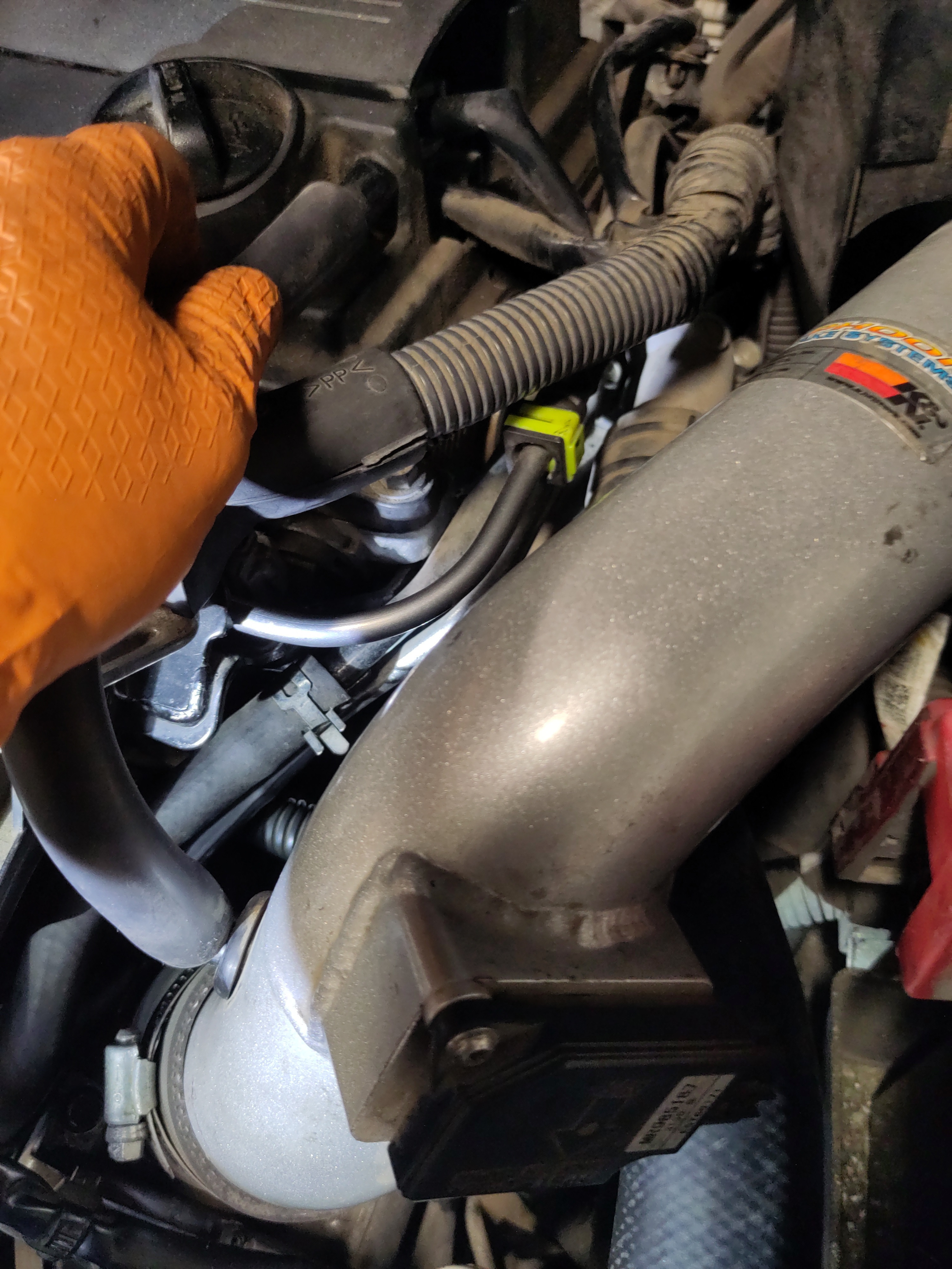
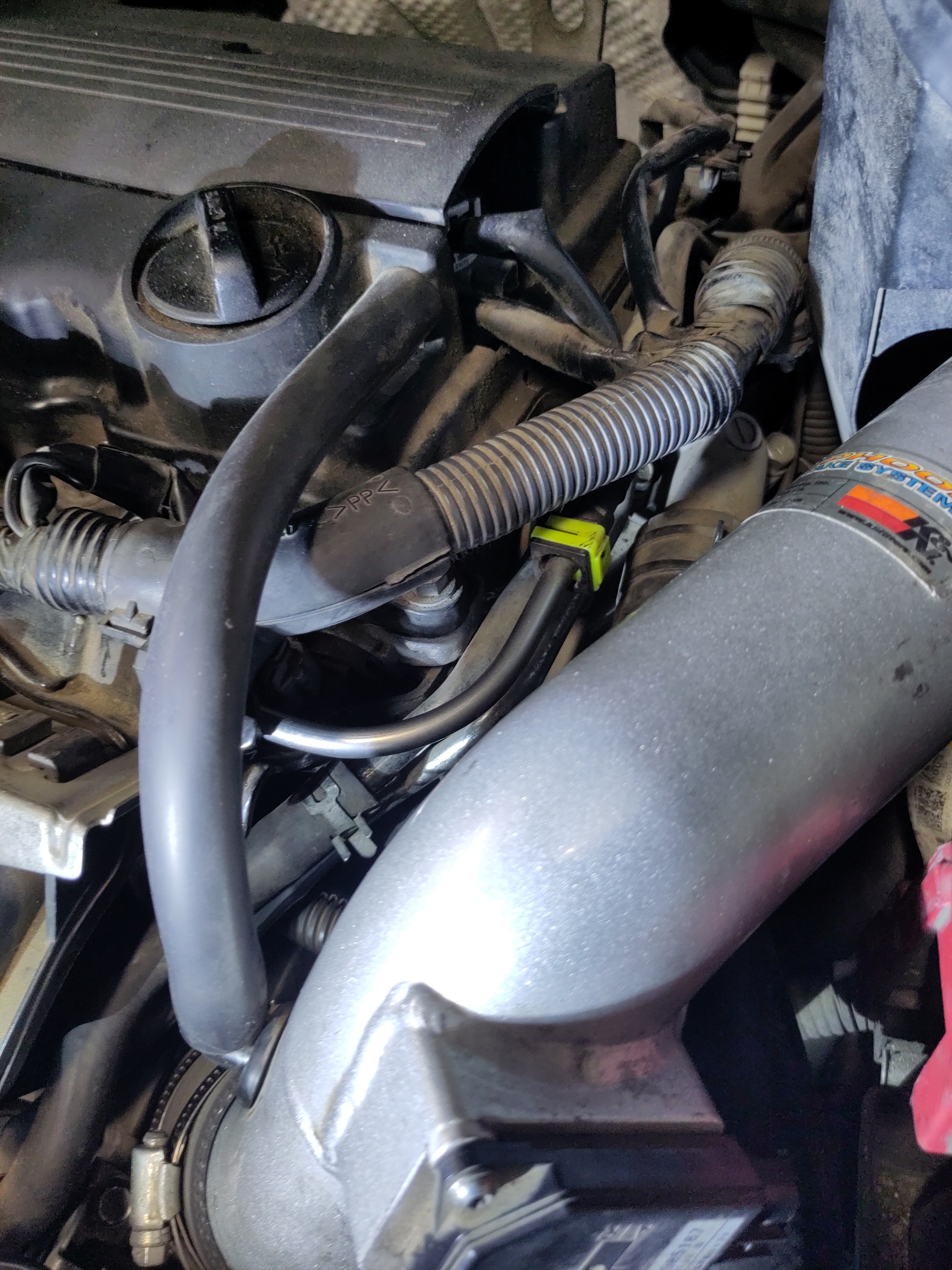
- Take the other 10mm bolt with the washer and hand thread the bolt into the air intake pipe with the support arm. Do not tighten the bolt down yet.
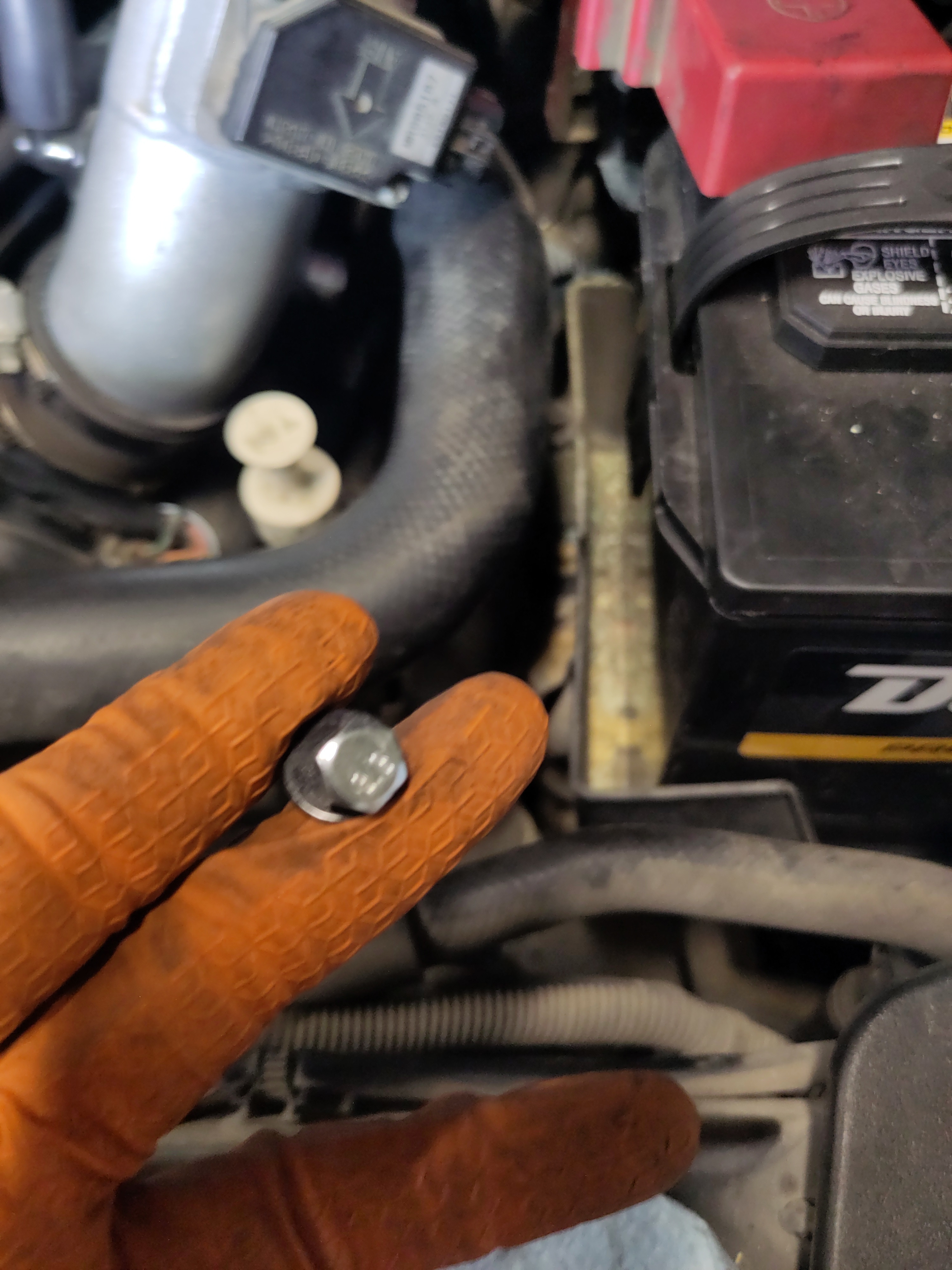
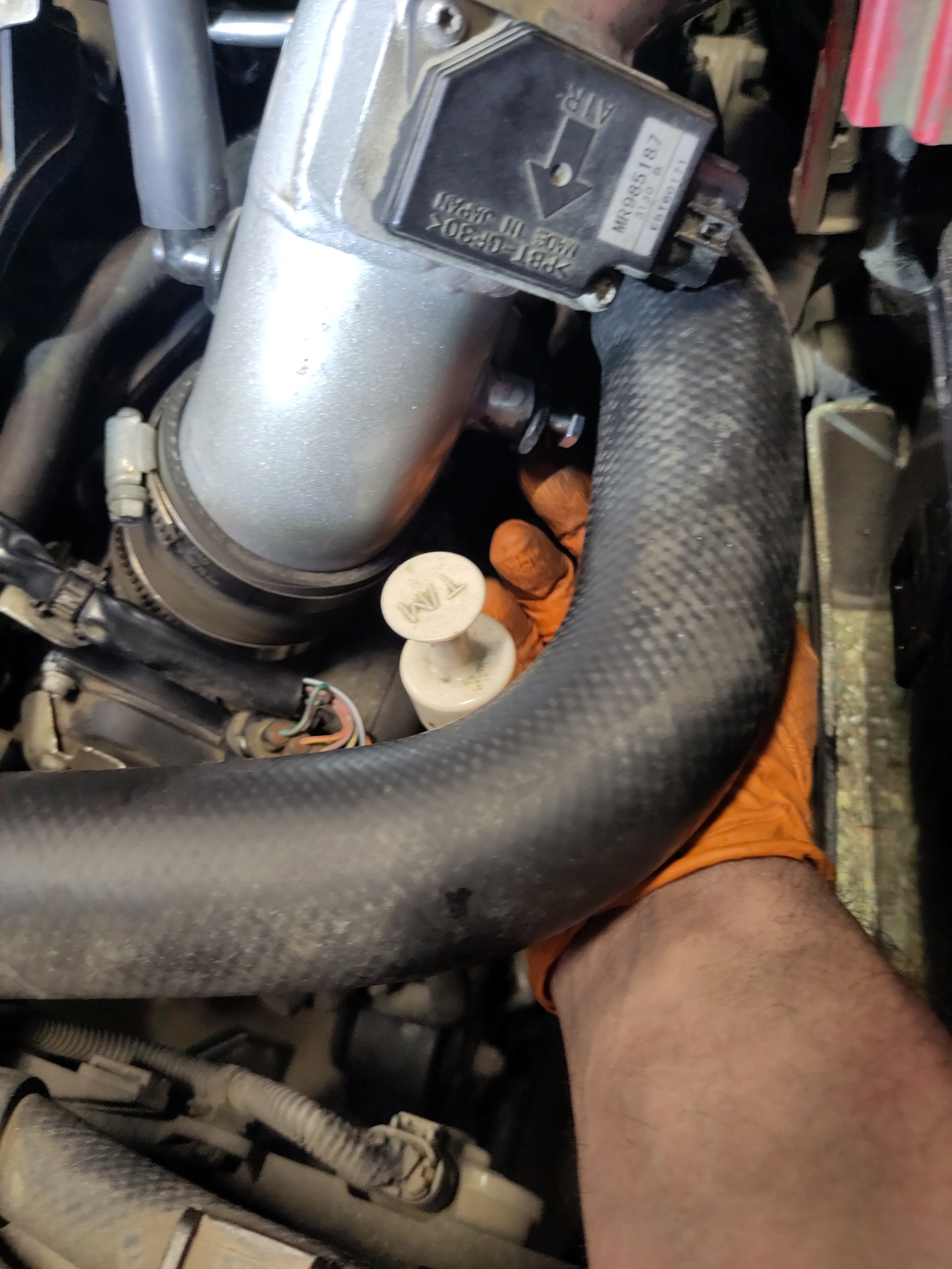
- Using the flat head secure the hose clamp. Make sure the hose clamp is tighten in the original position which can be determined by the indentation of the original position of the hose clamp.
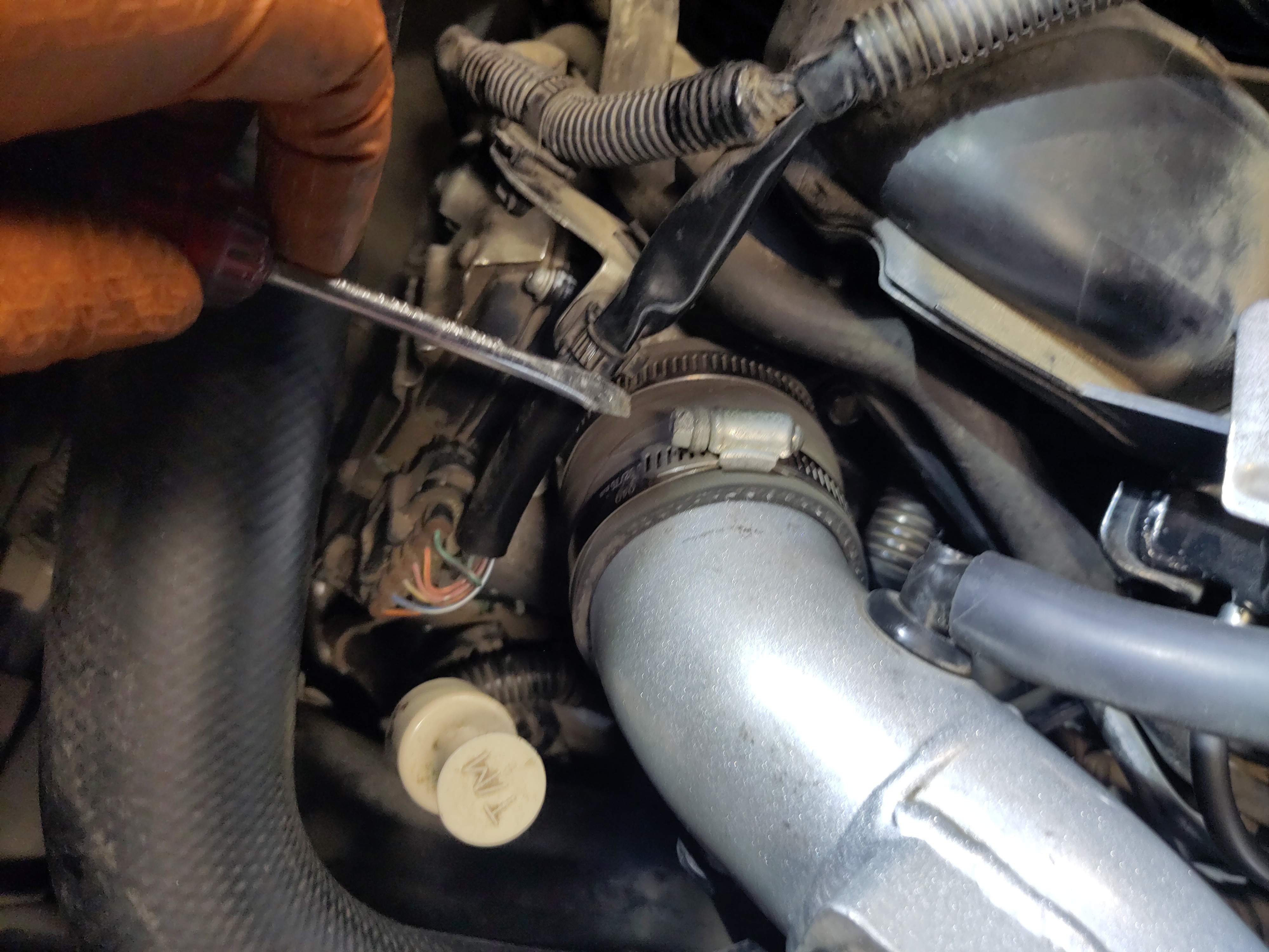
- Using the 1/4" drive socket wrench with a 1/4" drive 10mm shallow socket to secure both bolts to the support arm of the air intake pipe. I found it easy to secure the 10mm bolt onto the air intake pipe by placing the socket wrench behind the coolant hose this is illustrated in the pictures below. Also, the bolts just need to be snug, it is unnecessary to over-torque the bolts.
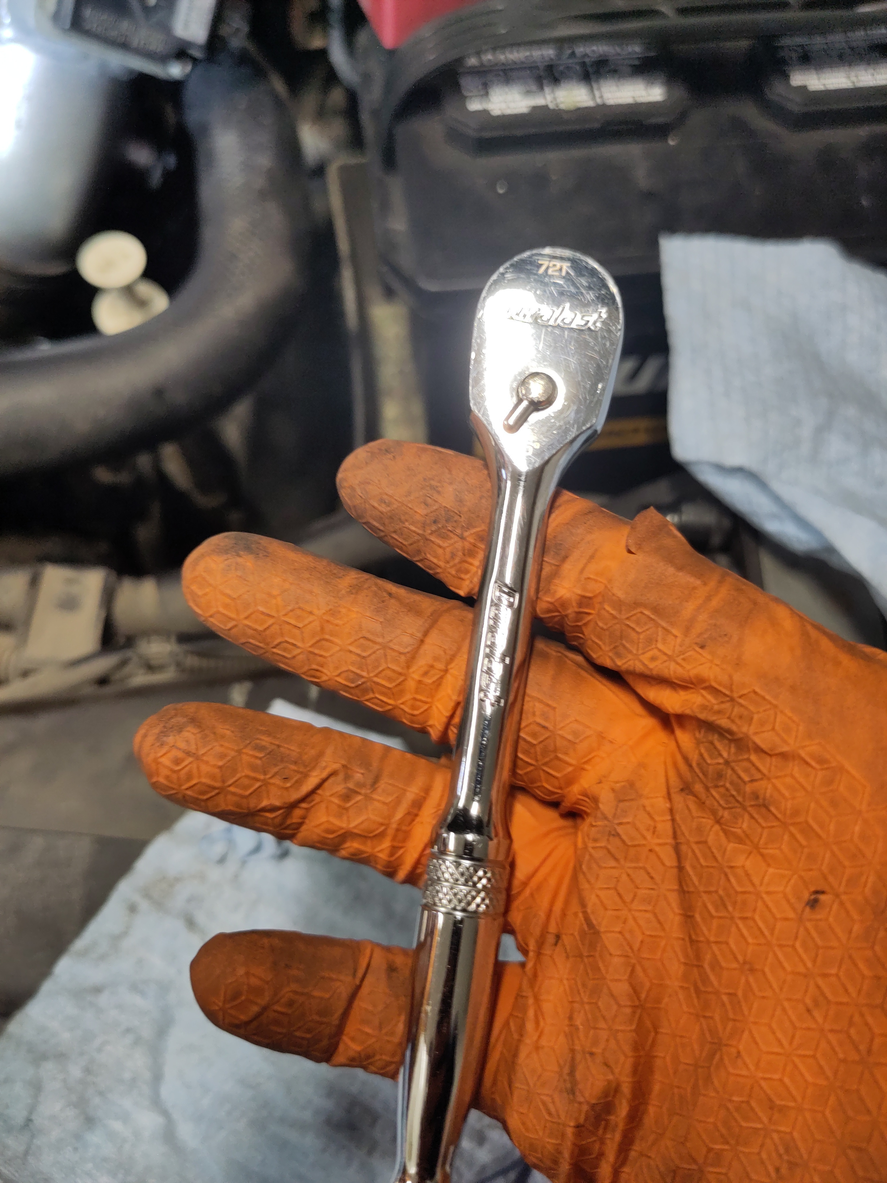
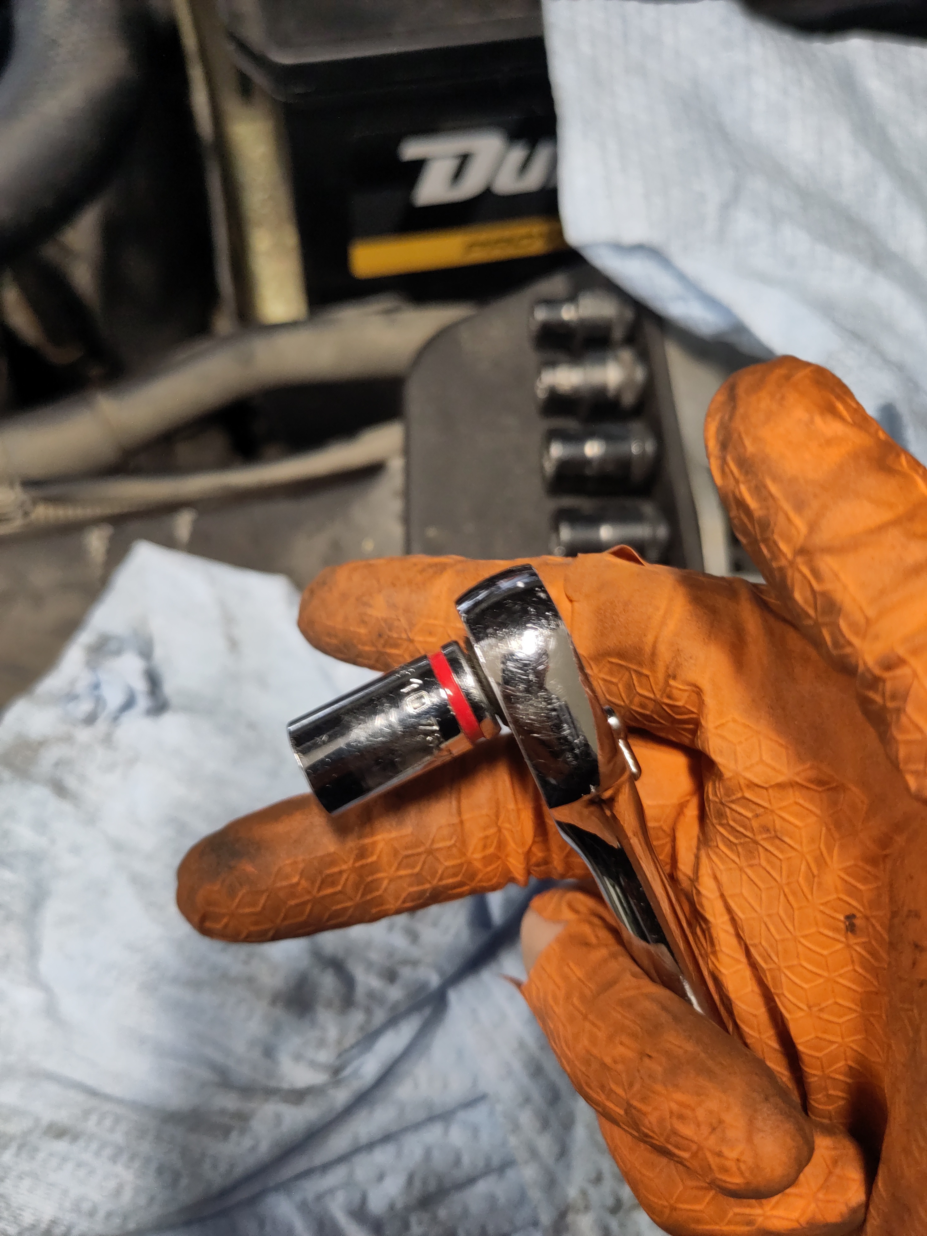
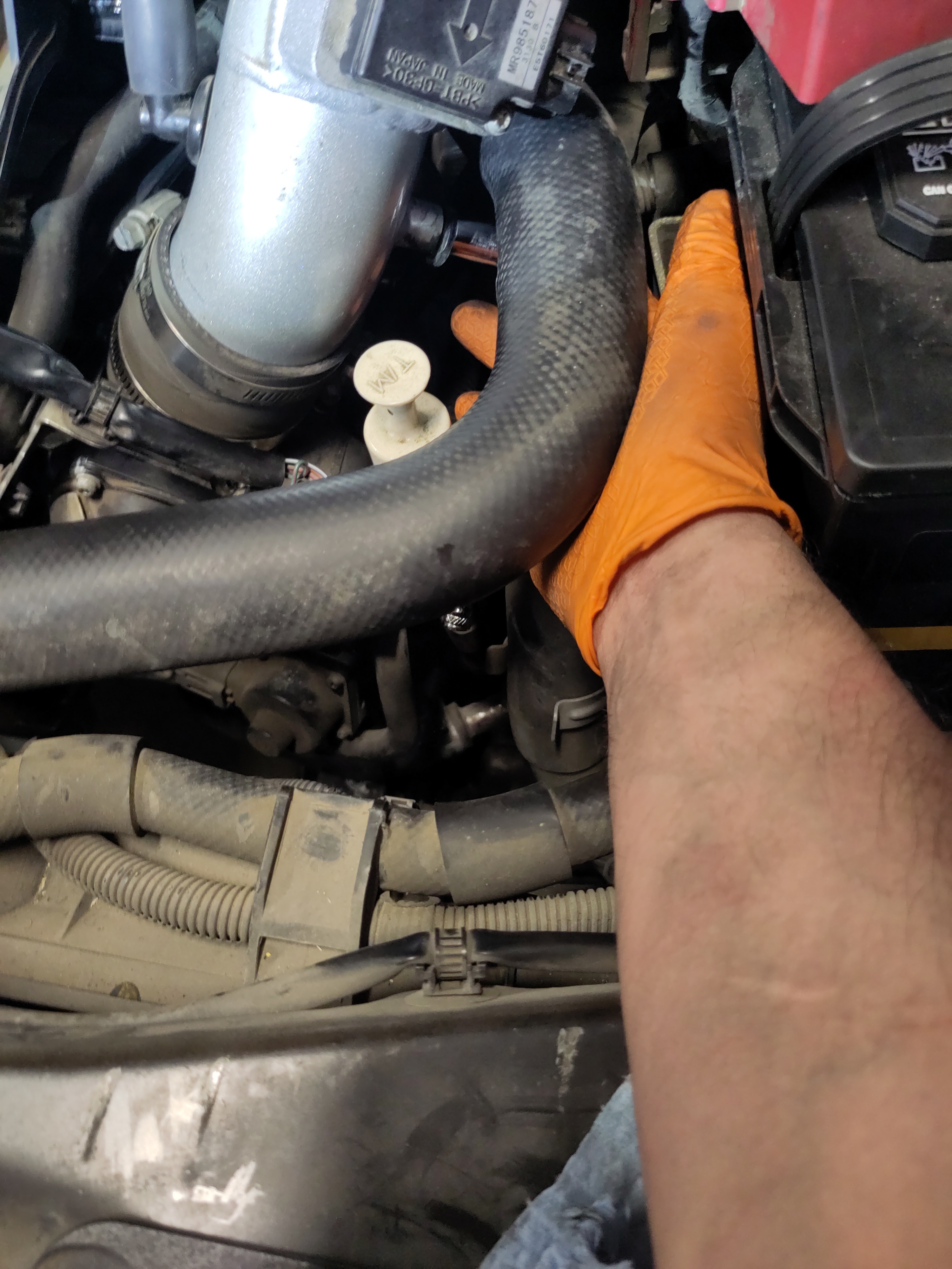
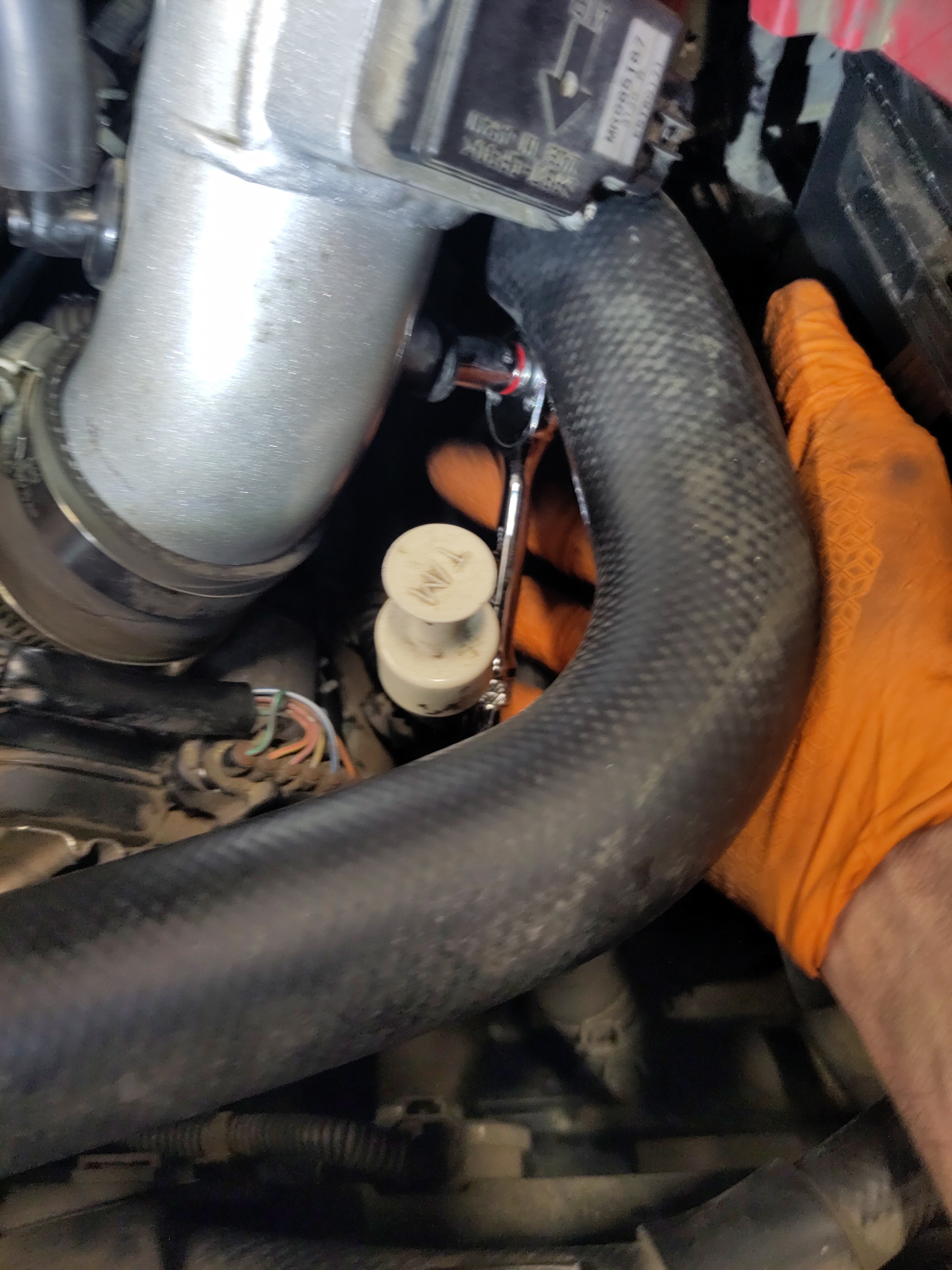
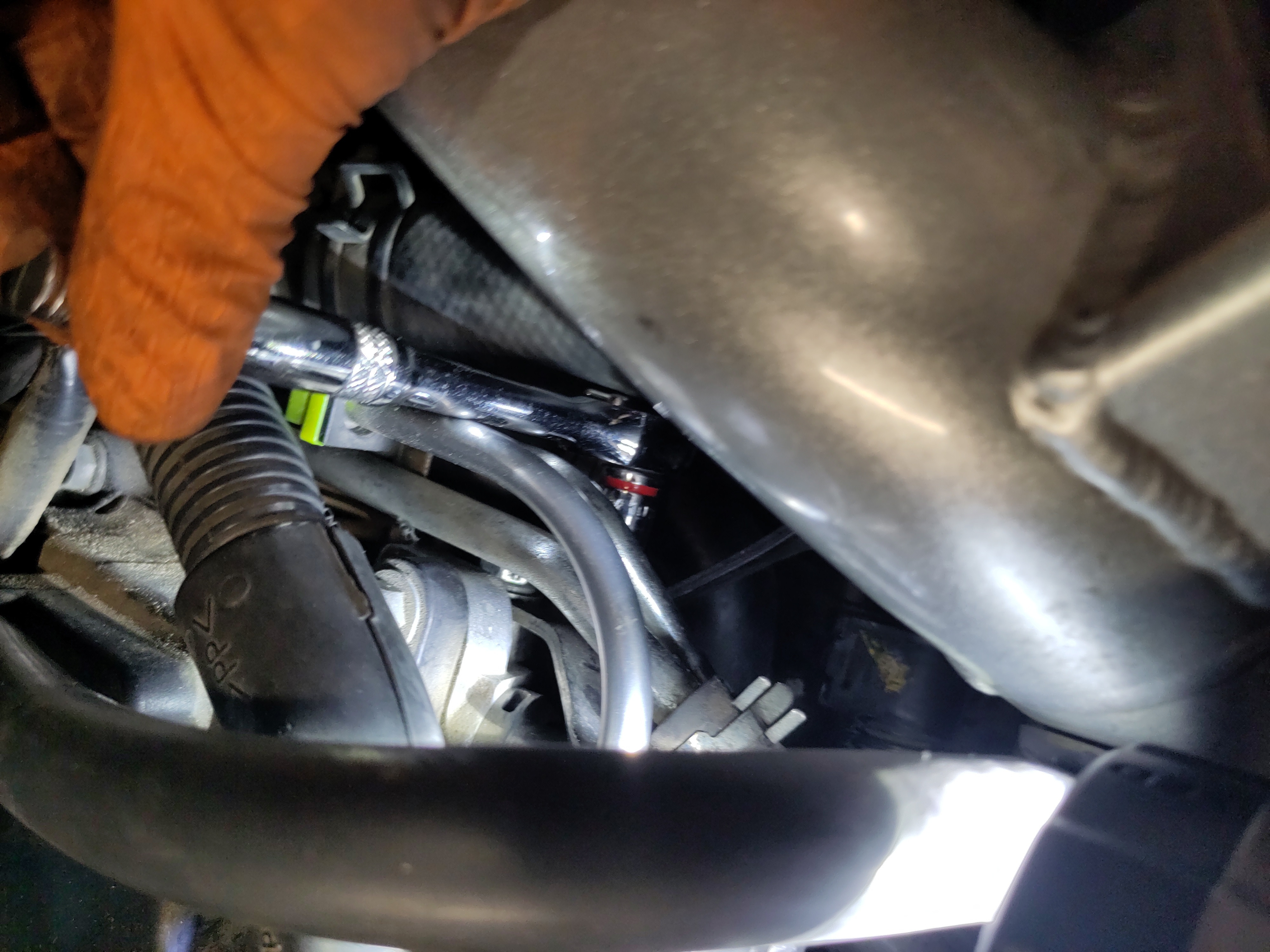
- The air filter now can be installed onto the air intake pipe. Make sure the air filter is on there snug and tighten down the hose clamp using a flat head screw driver.
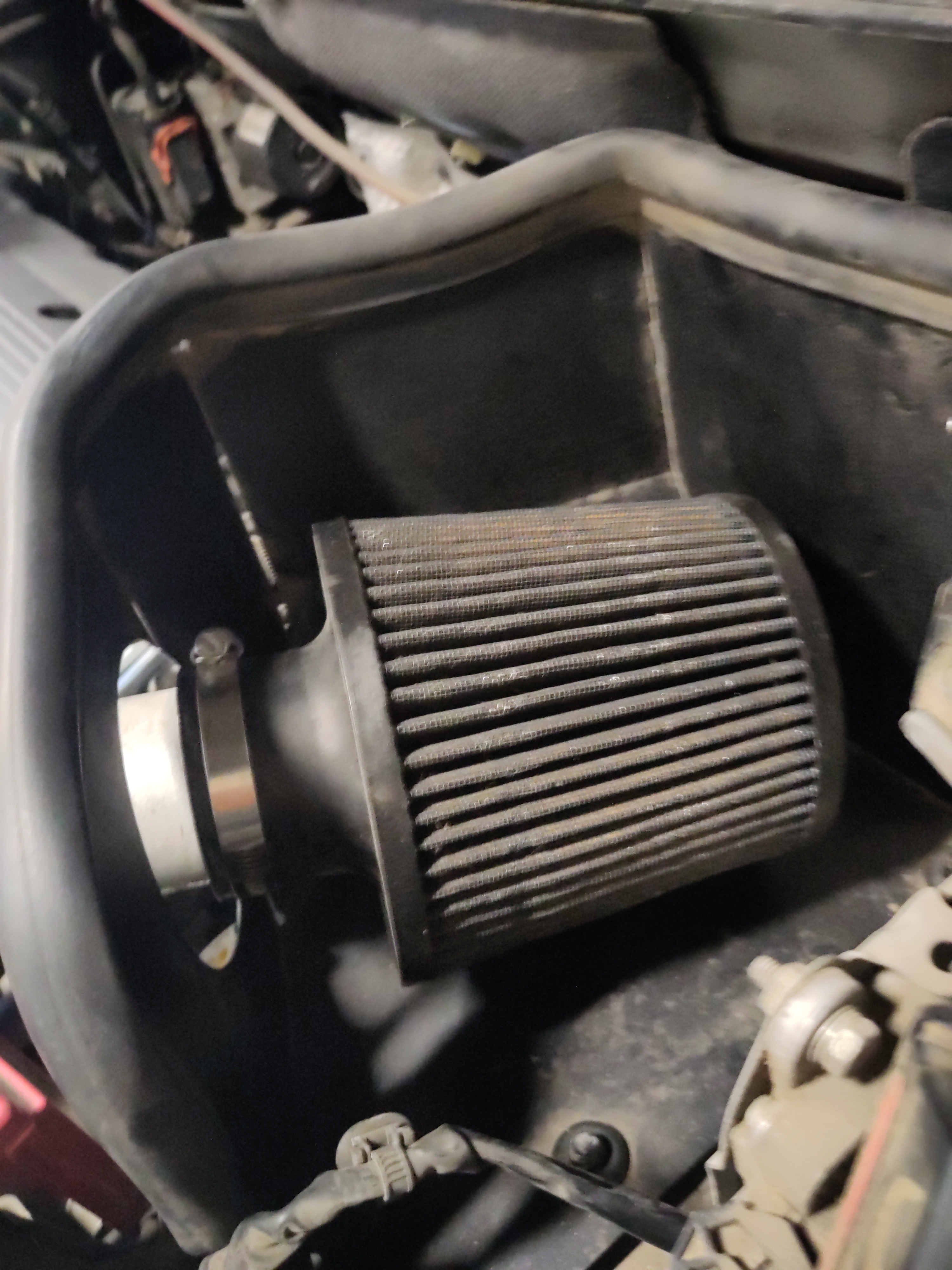
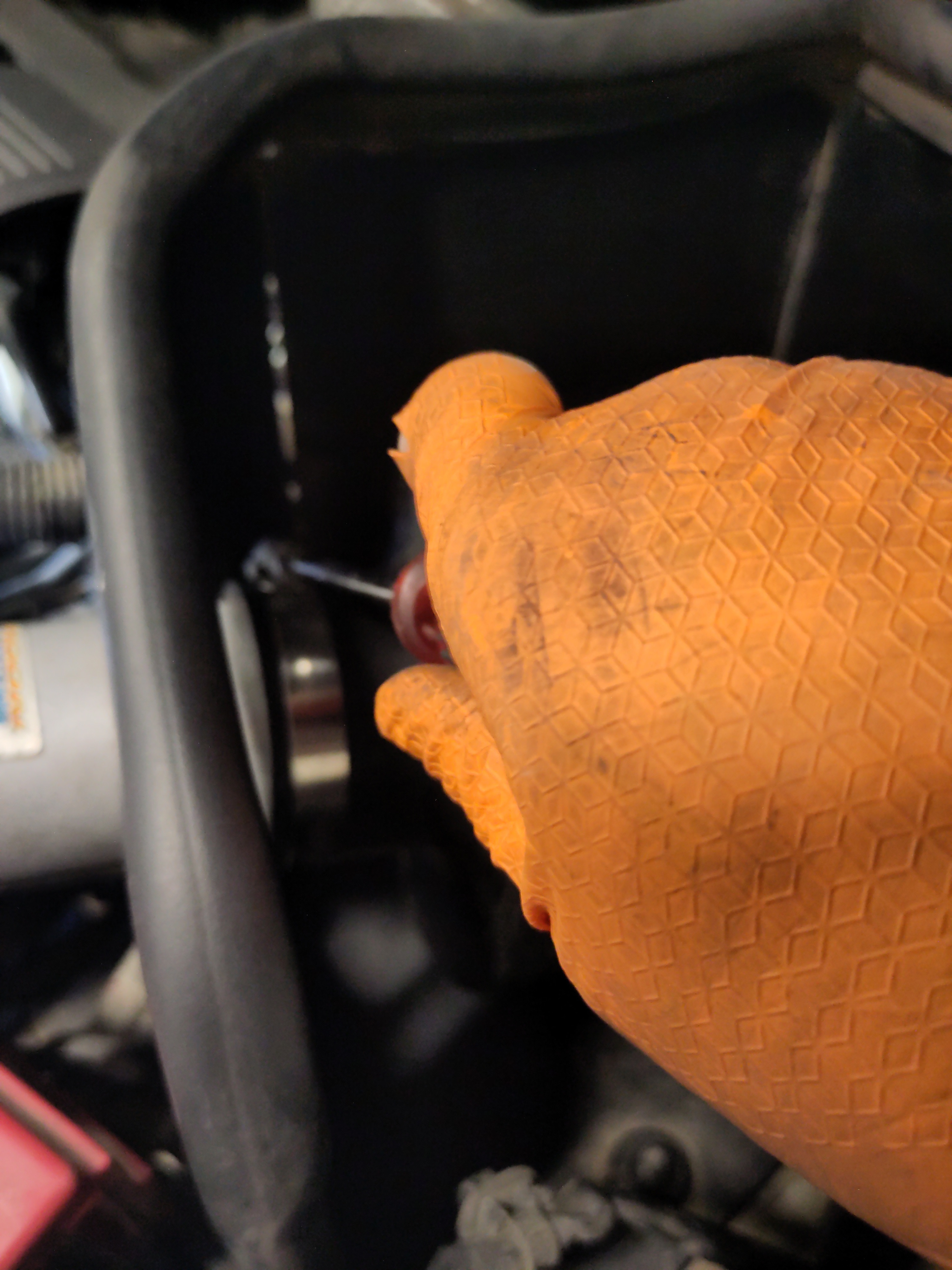
- Now apply some dielectric grease with q-tips to the mass air flow sensor electrical connection and connect the wiring harness to the sensor female end. There an audible sound make for confirmation of the secure connection.
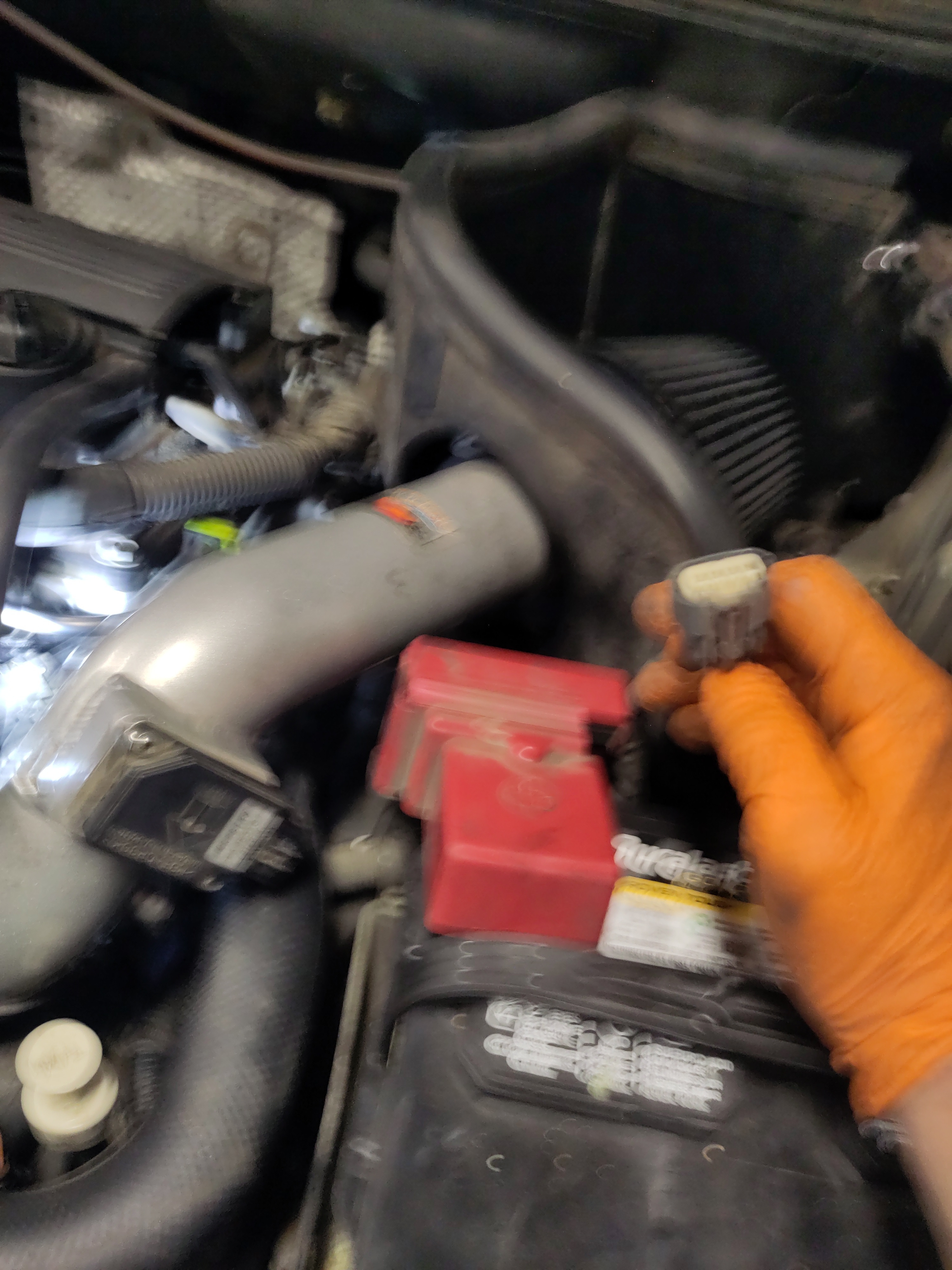
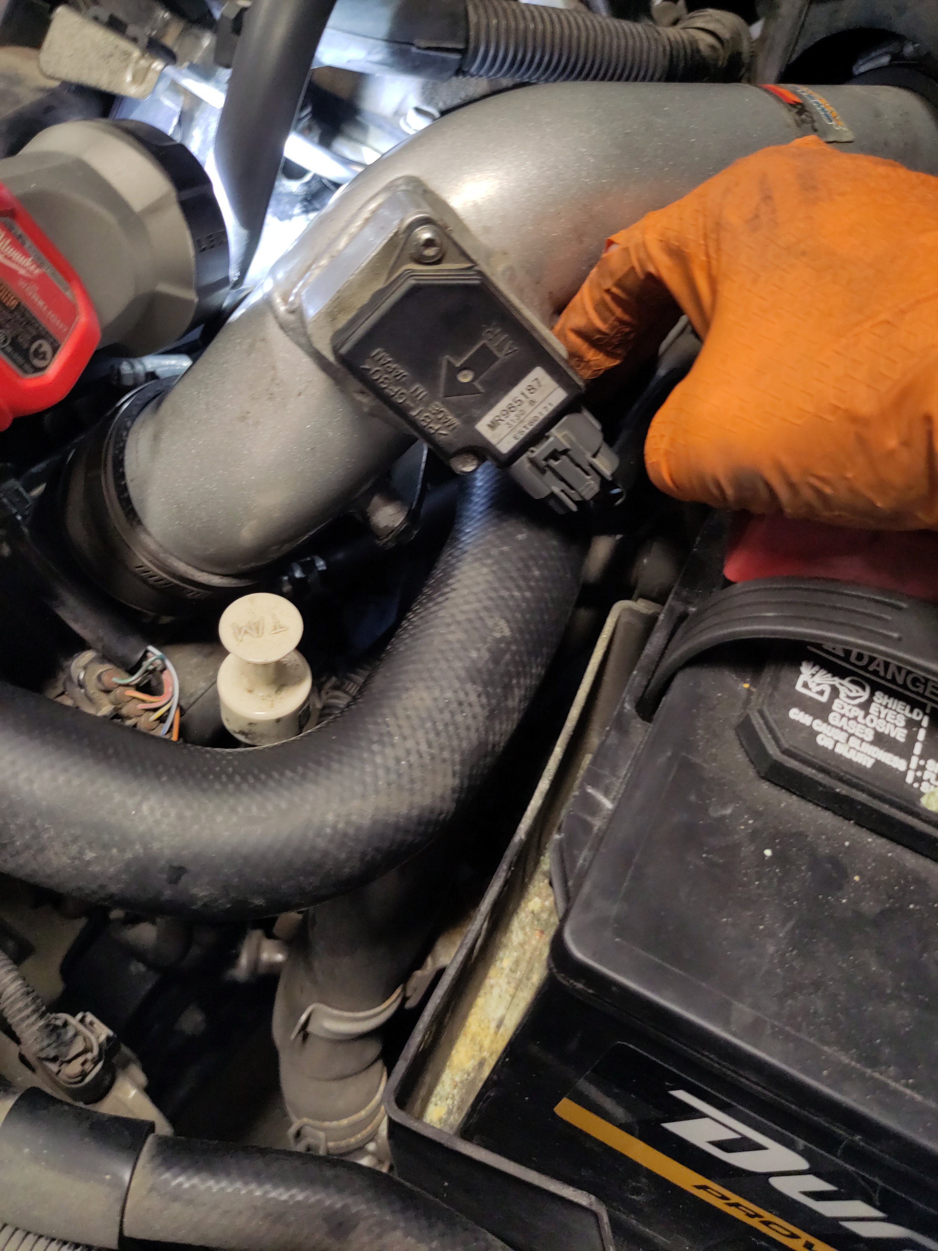
- Take the air intake plastic vent and secure it with the push pins.
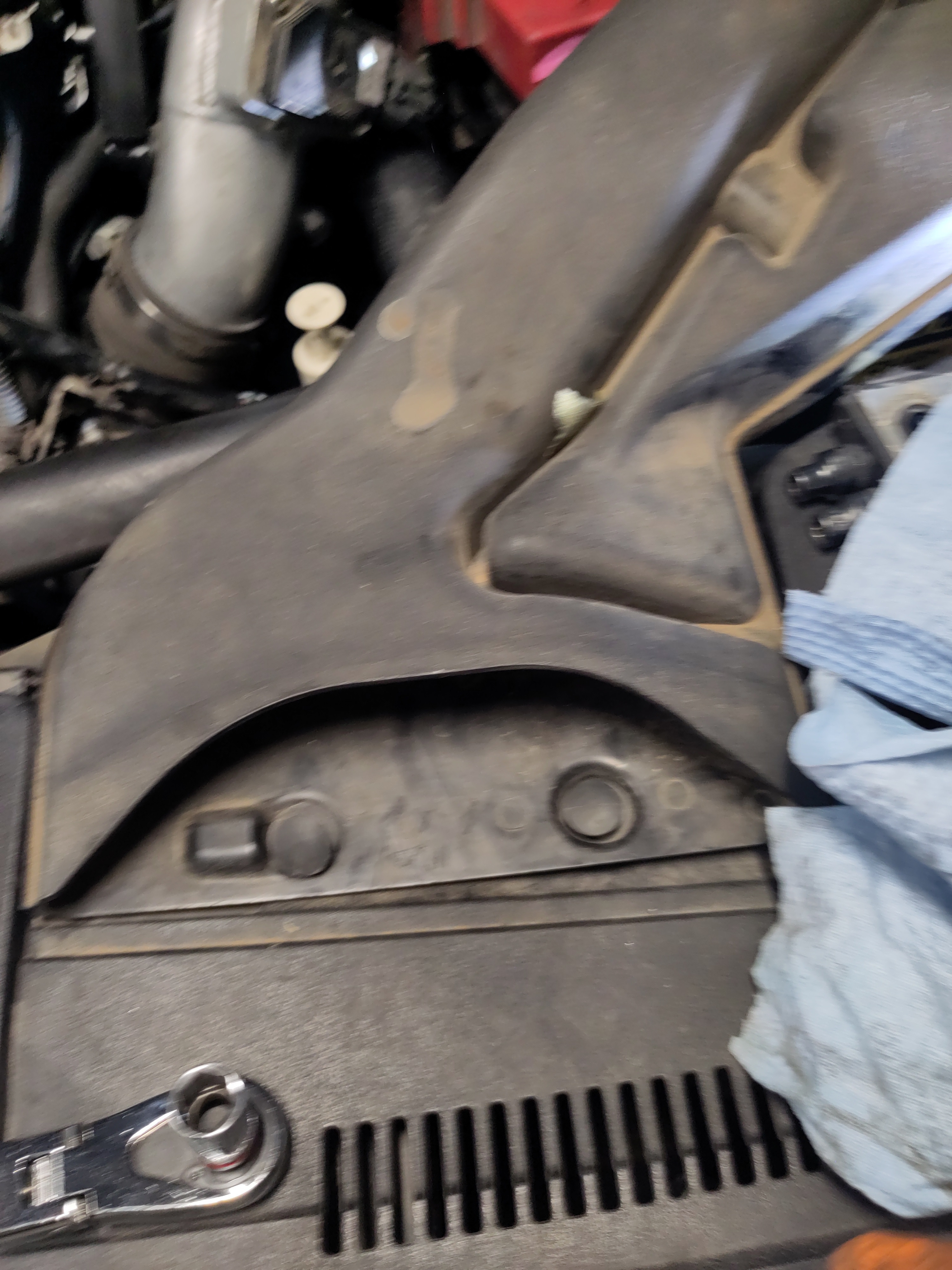
- Add the plastic vent connection to the air intake vent. It should clip onto one another.
- Finally it is time to reconnect the negative electrical connection to the negative battery terminal, and secure it using a 10mm open ended wrench. It also is a great idea to apply some dielectric grease to both terminal to mitigate corrosion build up.