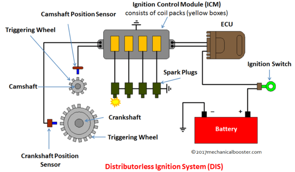
Purpose and Functionality:
The relevancy of the crankshaft position sensor(CKP) is to actively monitor and send live data to E.C.M. The E.C.M. is the centralized computer to oversee the operation and functionality of the ignition system. The E.C.M. is responsible for orchestrating lines of communication to individual components. The crankshaft positioning sensor measures the current position of the crankshaft which actively dictates on the current positioning of the pistons. For normal operation, the positioning and timing of the crankshaft is an imperative element in maintaining synchronization across the entirety of the system. When the Crankshaft is in the correct position or the timing is correct; a signal is sent to the E.C.M. In turn, the E.C.M. will send a signal ignition coil which will create strong enough current to create a spark from the spark plug when it is time appropriate.
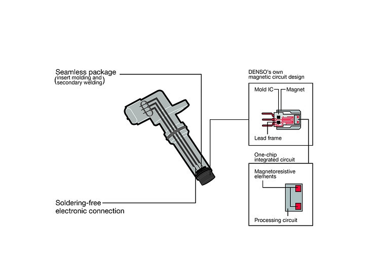
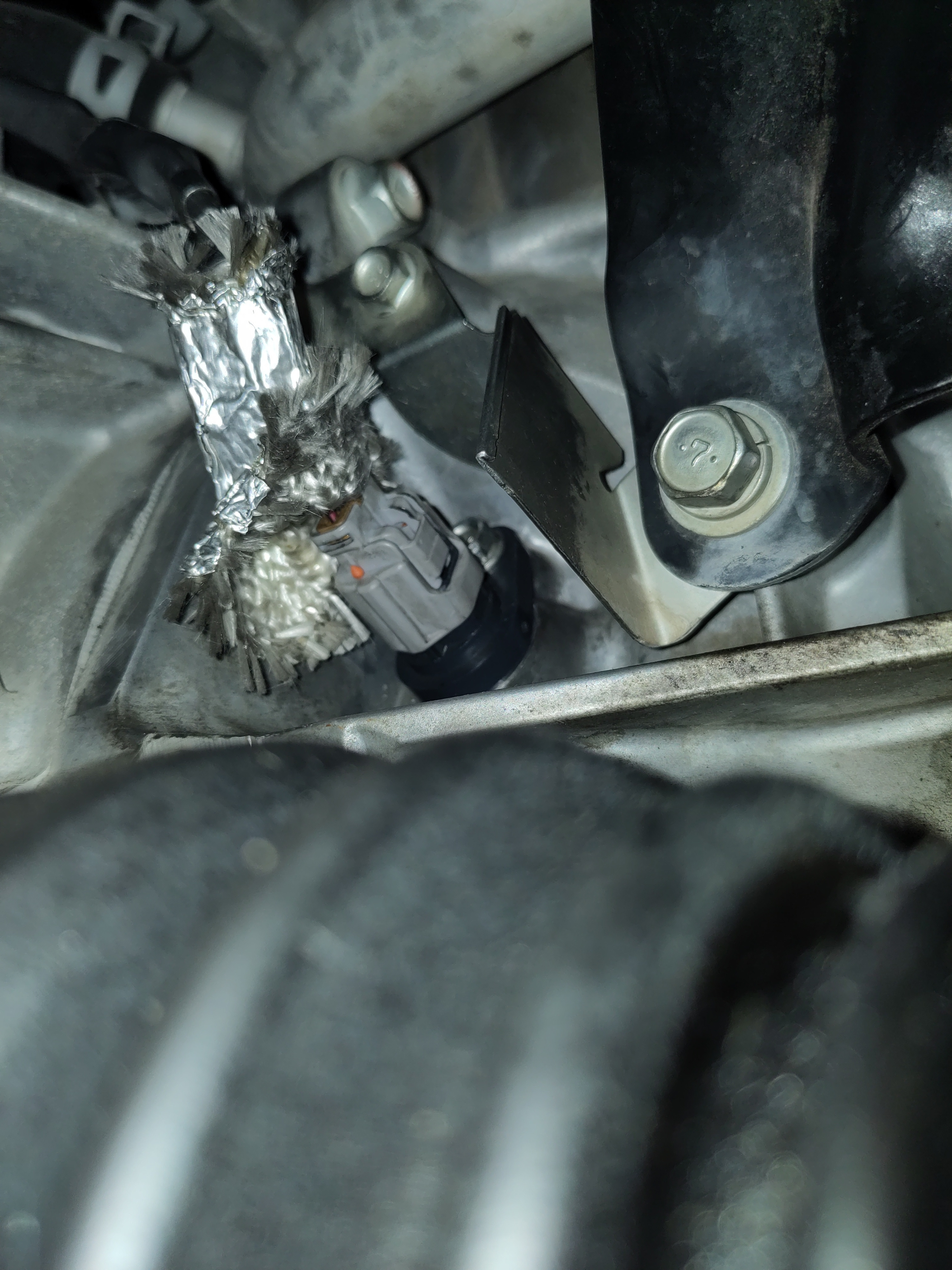
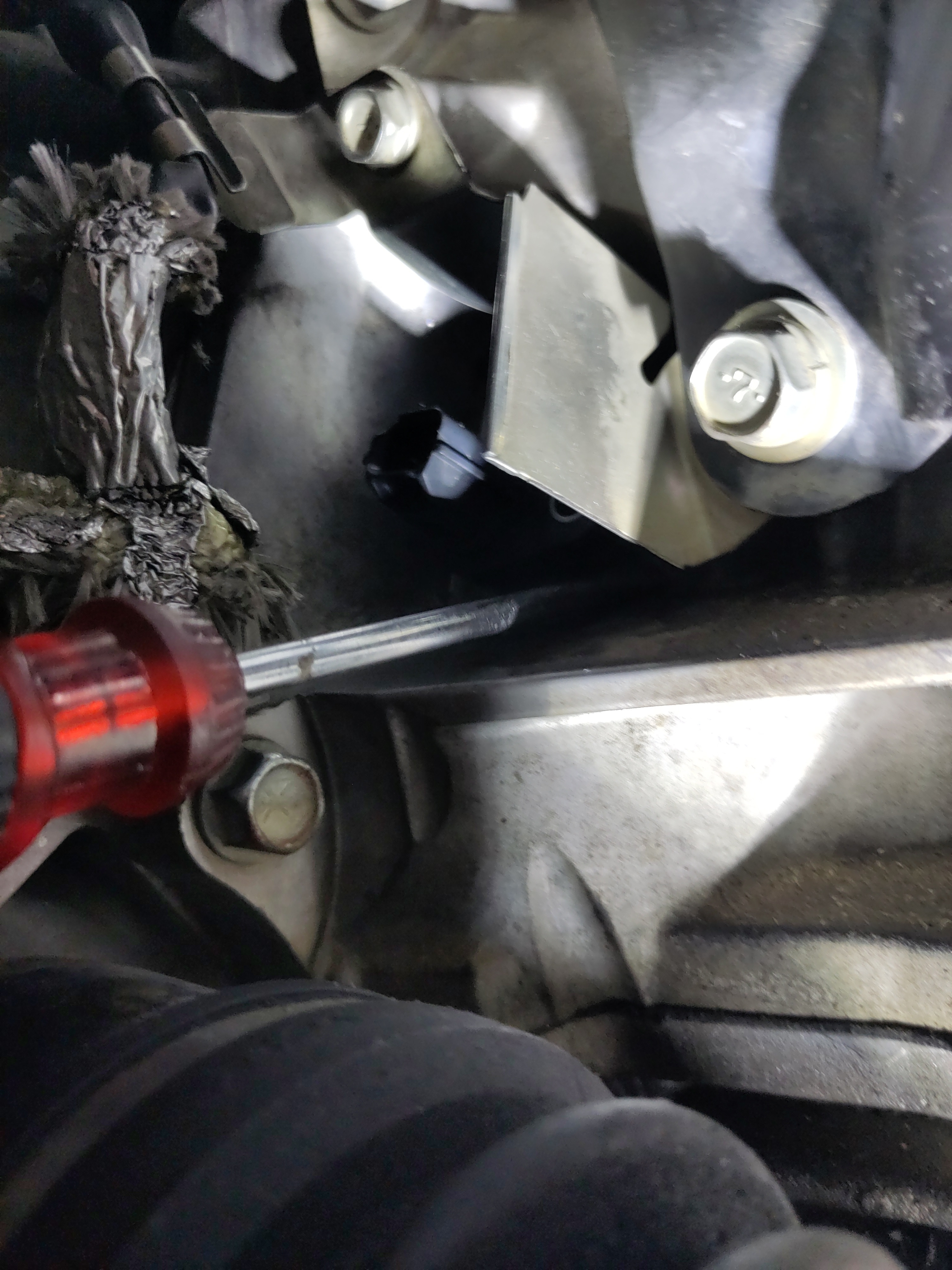
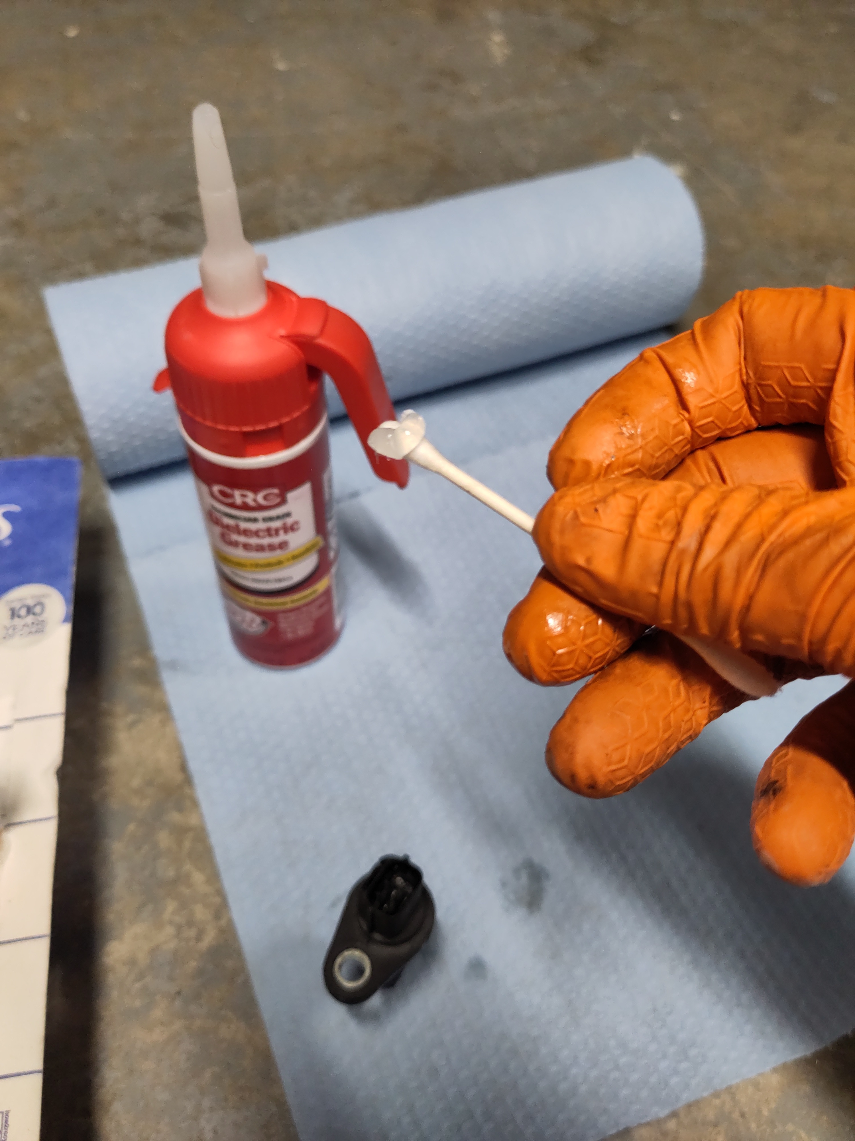
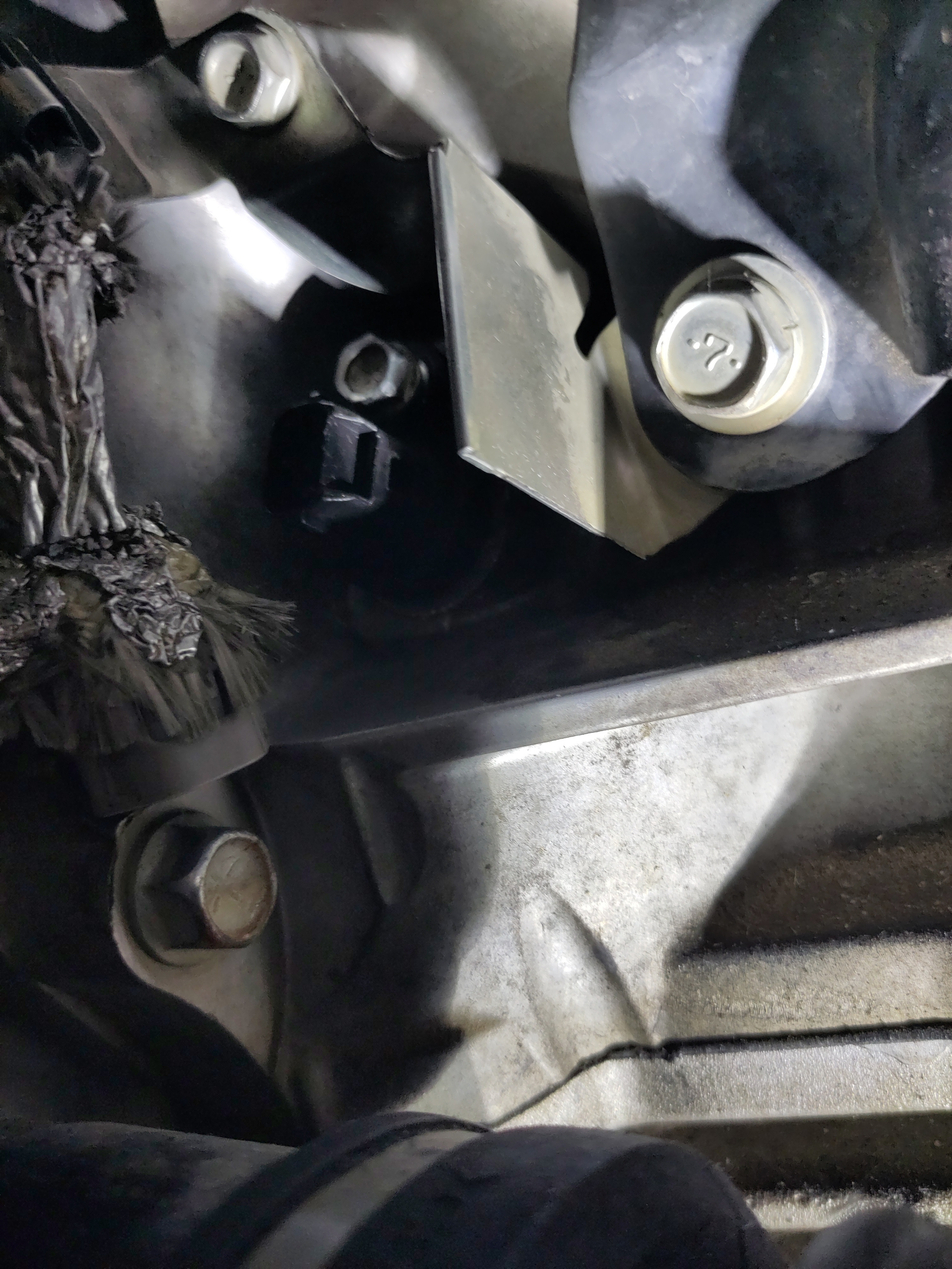
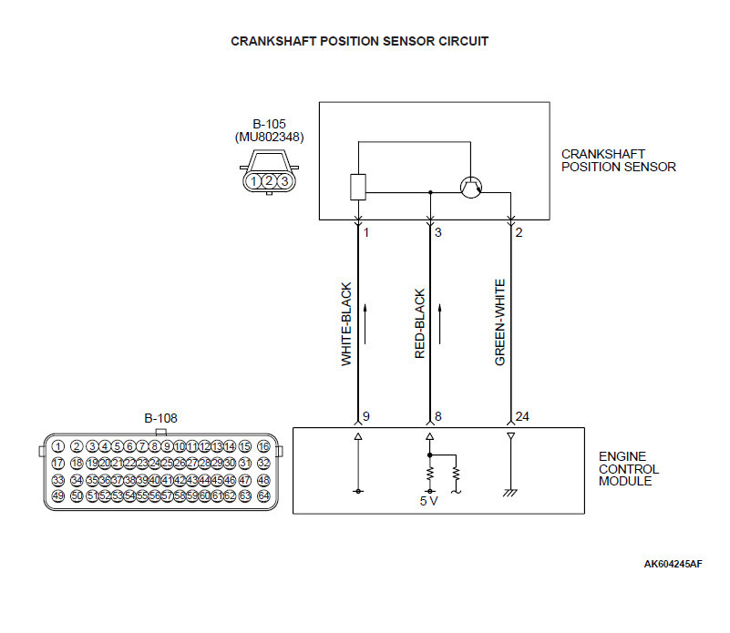
The inner operations of the crankshaft position sensor has an air gap separating the sensor from the gear. The inner mechanics of the crankshaft position sensor has a magnet or solenoid wire, it is strong enough to generate a voltage from the gear teeth which is measured from the processing chip. The processing chip measures the data with like a manual light switch. The data is transferred to the E.C.M. through the signal wire. In the 2013 Mitsubishi Lancer ES, there are three pins one is the positive, signal and the other is the ground. The signal wire is found in the middle. The connections can be determined from using a multi-meter and measuring the values coming from the E.C.M. connection side of the vehicle not the crankshaft position sensor. The diagrams below is based upon generalized designs and is not an applicable design to the Lancer. The schematic provides a generalized understanding of the inner operations and the circuitry and what other components constitutes to the sensor.

As show below, there are three wires connecting to the processing unit and the magnet. The positive and ground connections power the processing unit and it's required components. The signal wire is connected to the magnet, and transfers the voltage from the gear to magnet to the processing unit which converts the voltage to signal that can be determined by the E.C.M.